The other day I received my 100th Postcrossing postcard! I thought it appropriate to give an update to celebrate the occasion!
In the 10 months since I sent my first card I’ve received cards from 27 countries and sent them to 32. While I have sent cards to Australia, South America and South Africa, I have yet to receive any from there, so I’m still waiting to have a card from every continent (bar Antarctica of course). Here’s the stats:
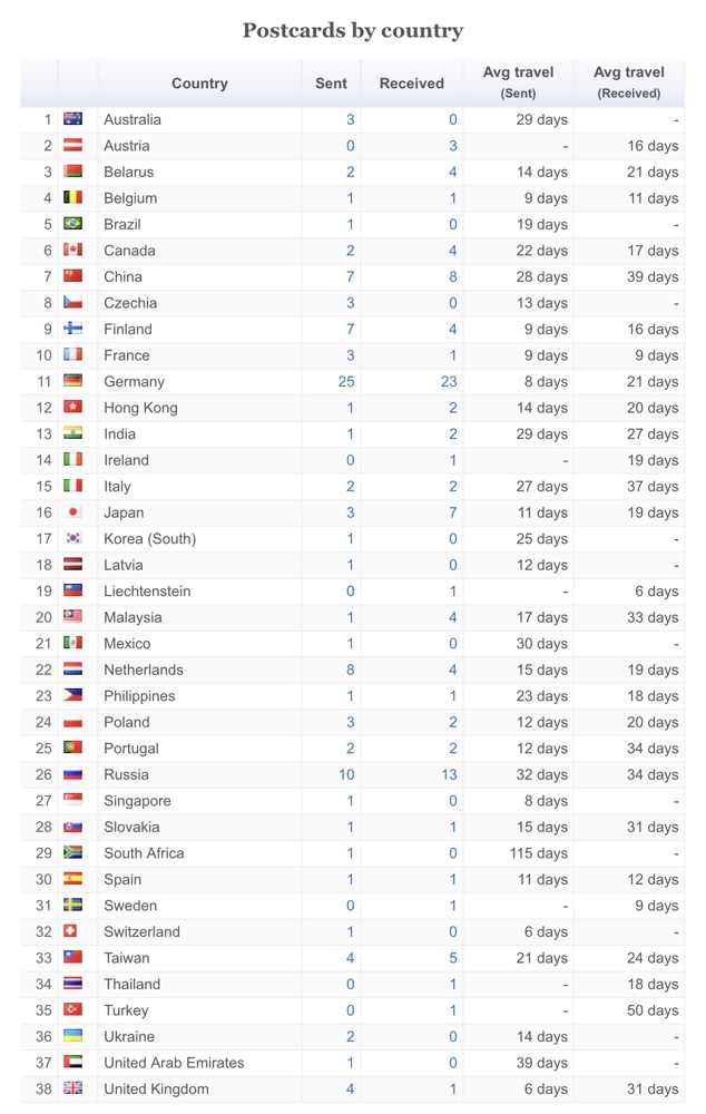
Cards ‘expire’ after 90 days, which means you can request a new address even if one doesn’t arrive. While the South African one was technically expired, it eventually arrived and was registered by the recipient who lives on a tiny island off the west coast of Africa and said his mail service is sporadic! I’ve had three other expired cards to date, all to Eastern European countries.
You can see Germany is above and beyond the most popular country for Postcrossing, but I have to say I’m most surprised by China. While it’s a bit scary to be given addresses in that country (since it’s difficult to write Chinese characters!) I’ve never had one not arrive so I must be doing ok 🙂
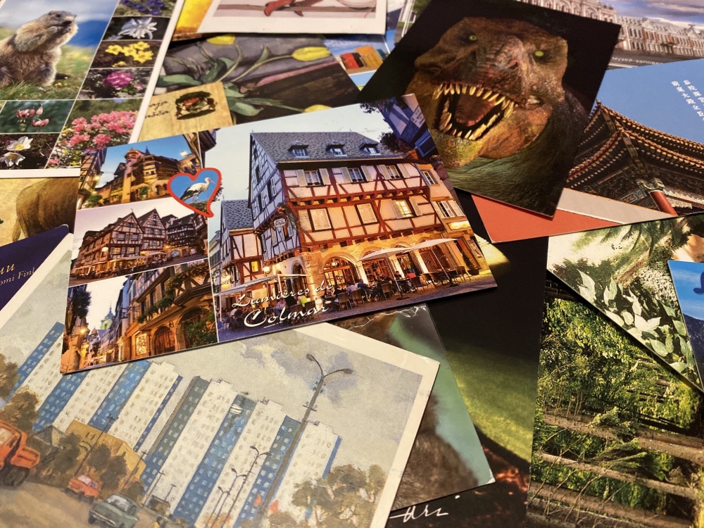
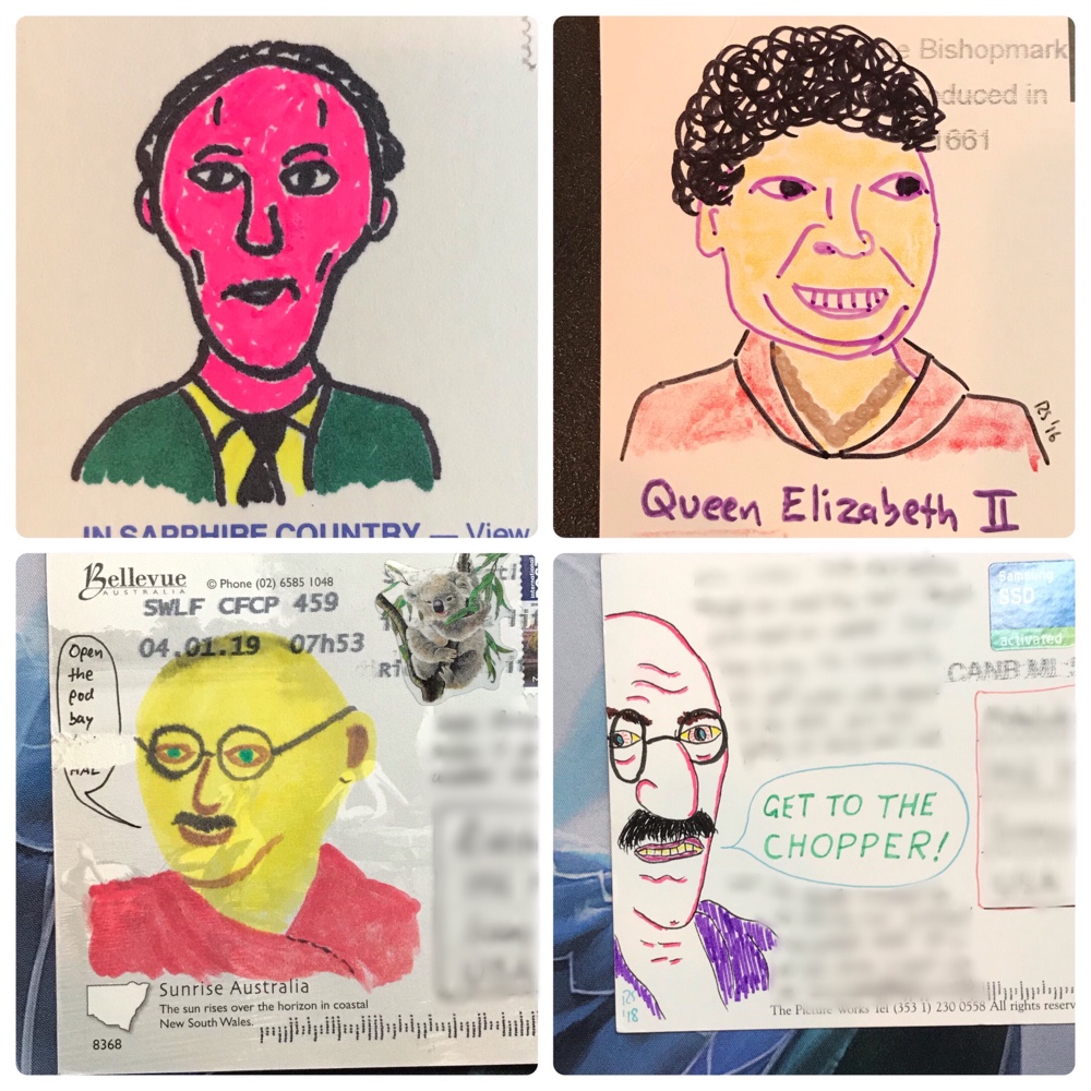
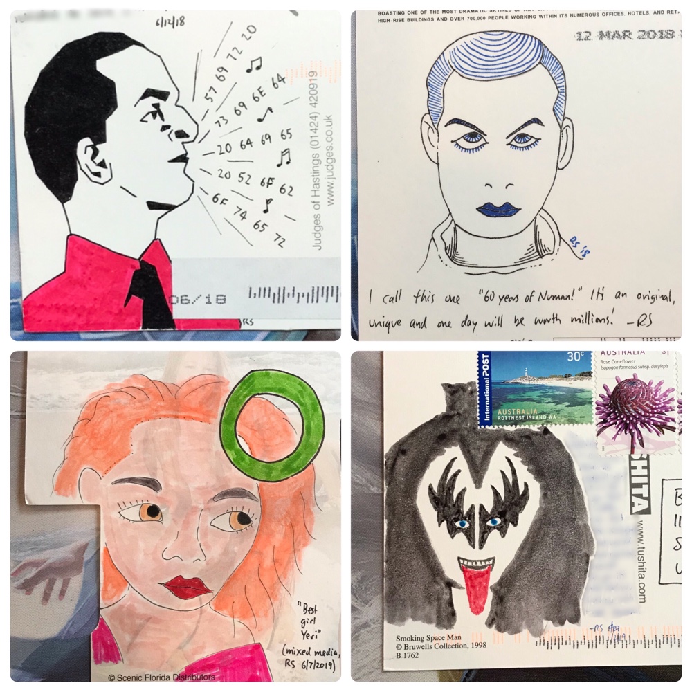
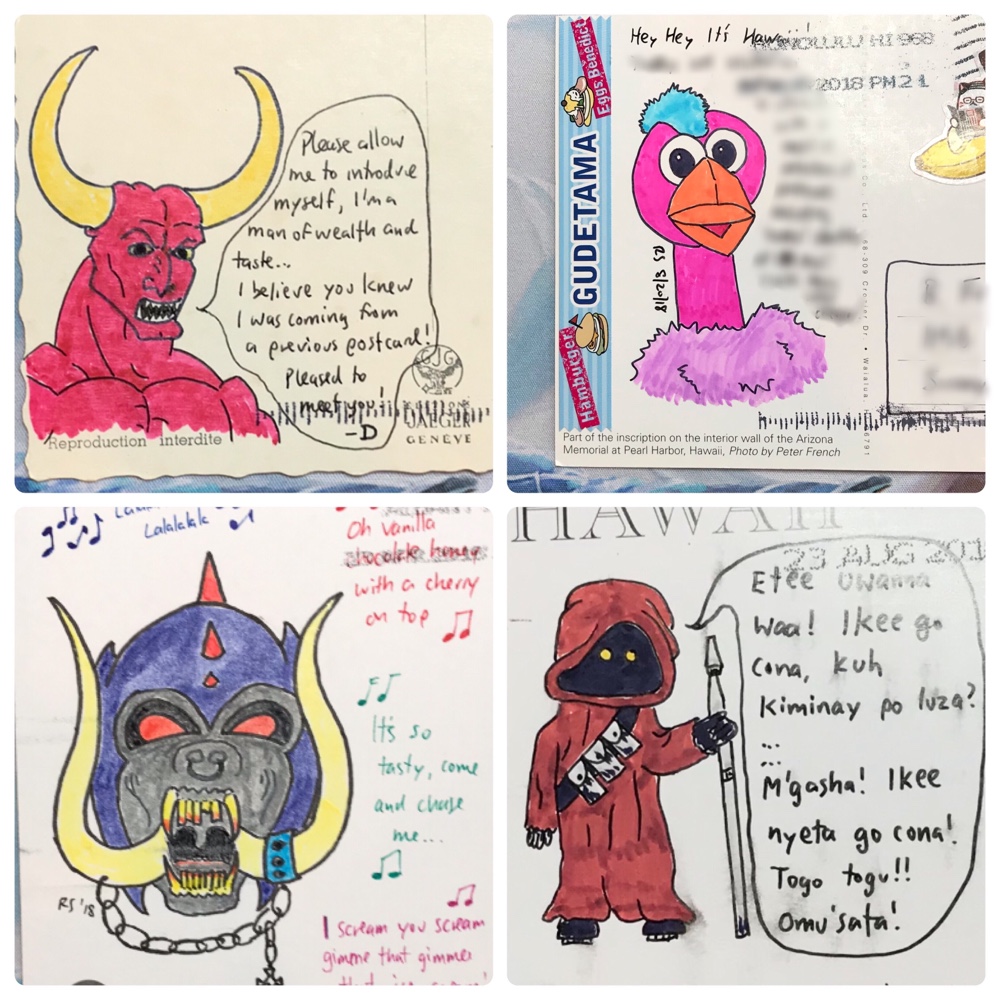
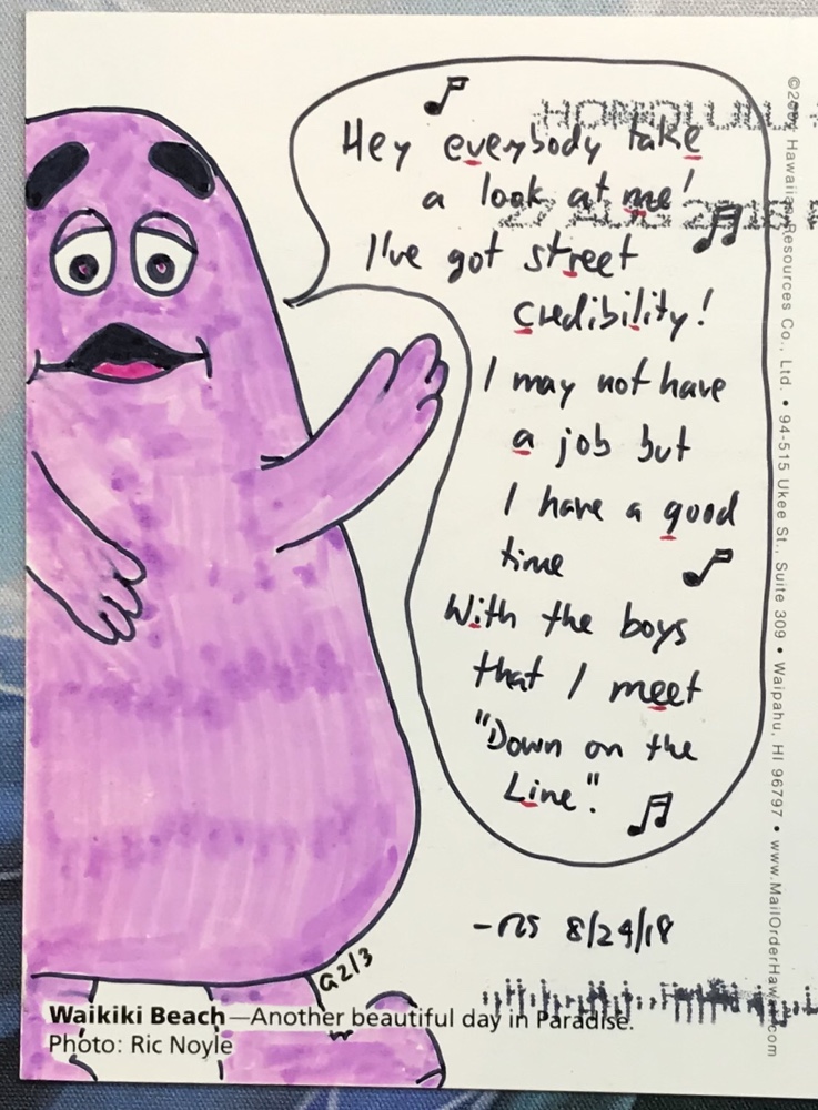
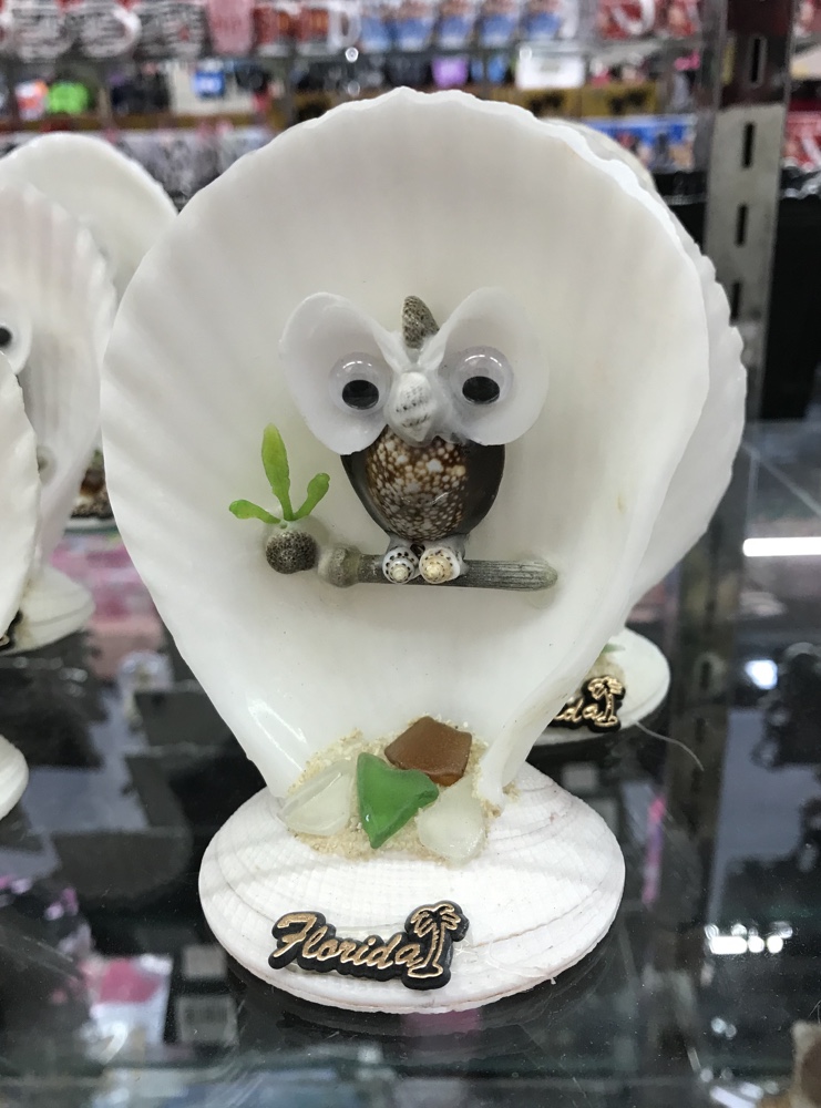
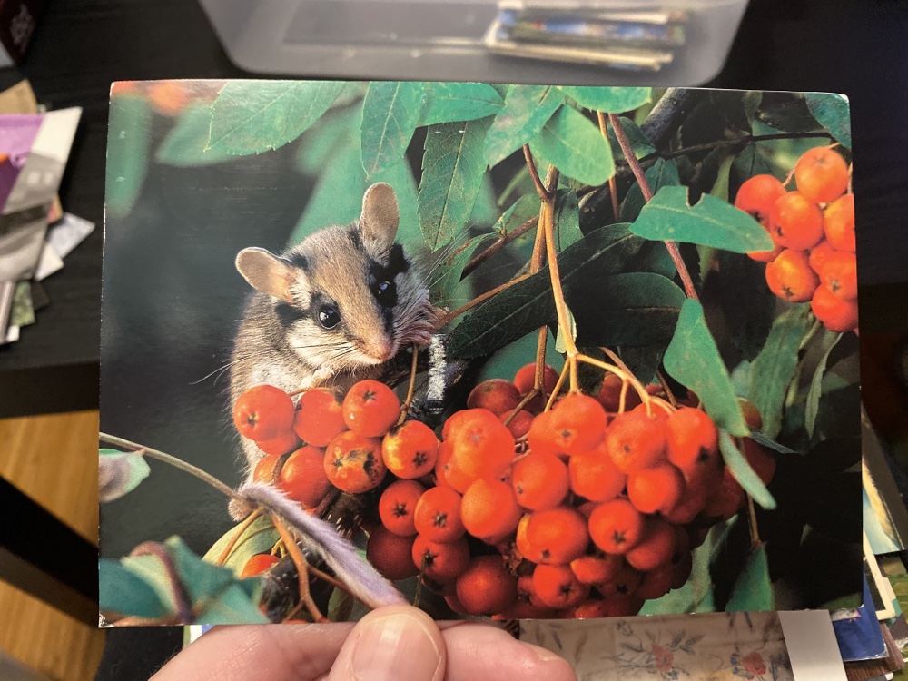
The cards themselves run the gamut, but since I have requested classic tourist cards, animal cards and pinup cards I tend to mostly get those. I’ve made it clear I’m interested in the stamps as well and get a great selection from all over the world.
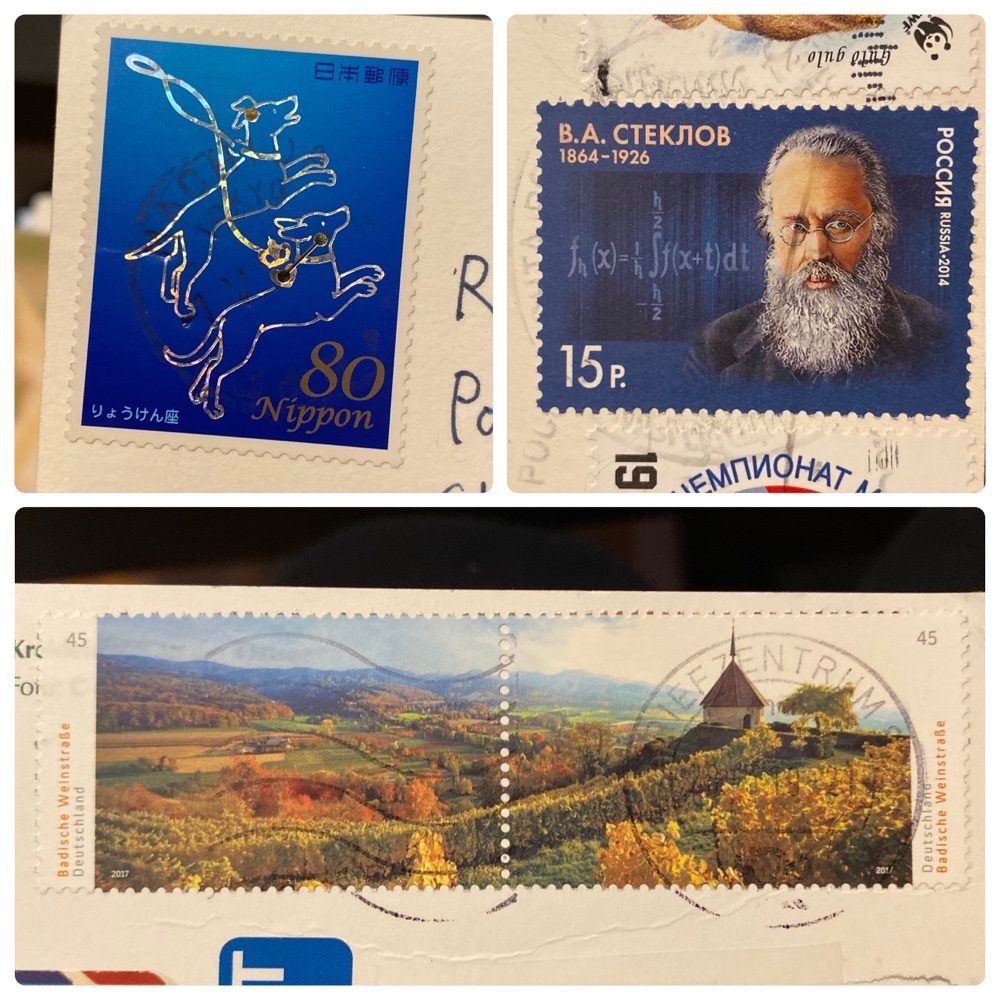
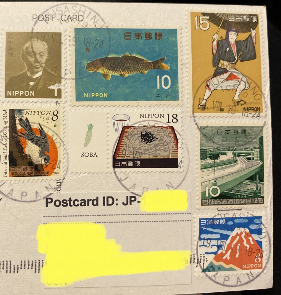
The Russian scientist stamp is great isn’t it? Germany has a few series of lovely connected landscape stamps and Japanese stamps are always graphic and very pretty. Take a look at the effort this guy put in to cram as many stamps as possible on his card from Japan:
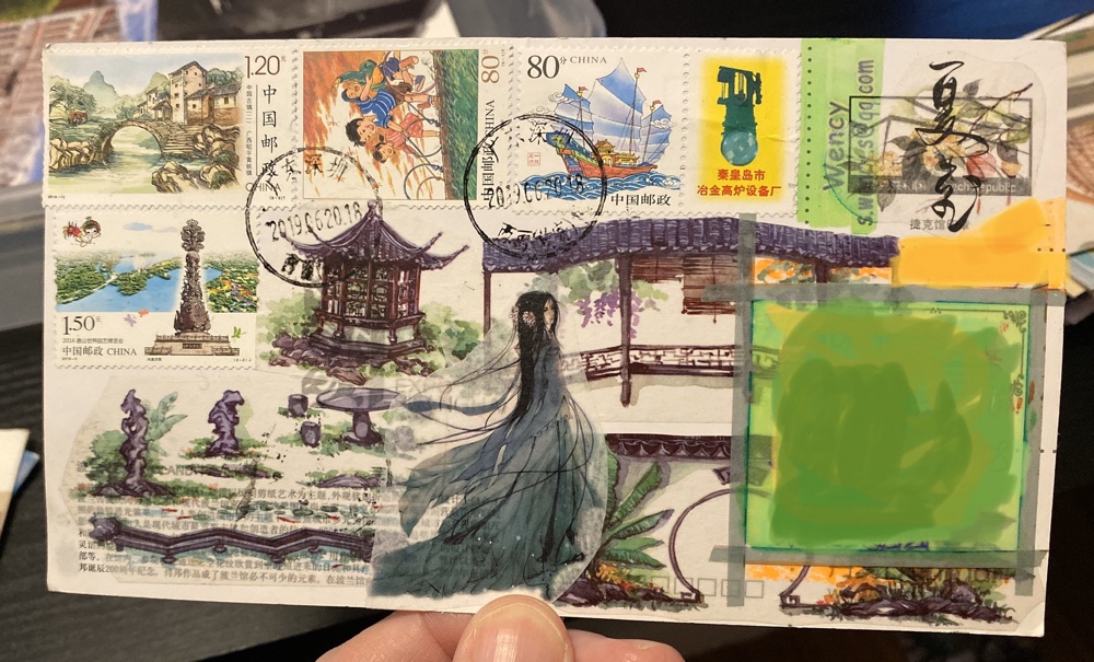
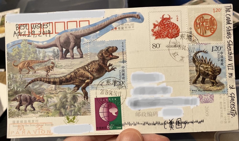
Or these two Chinese cards:
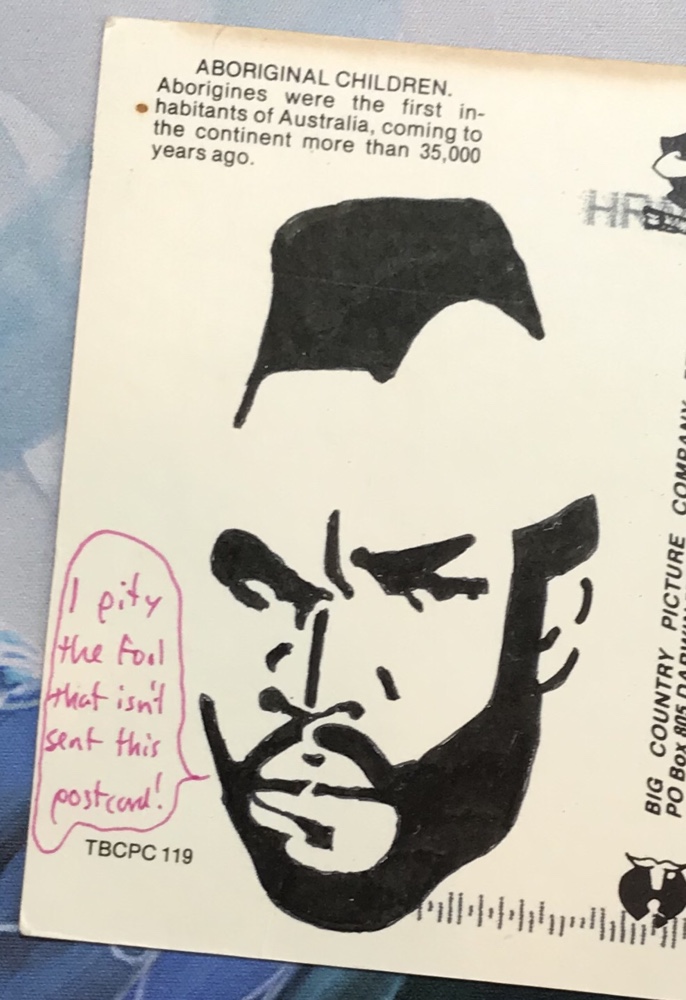
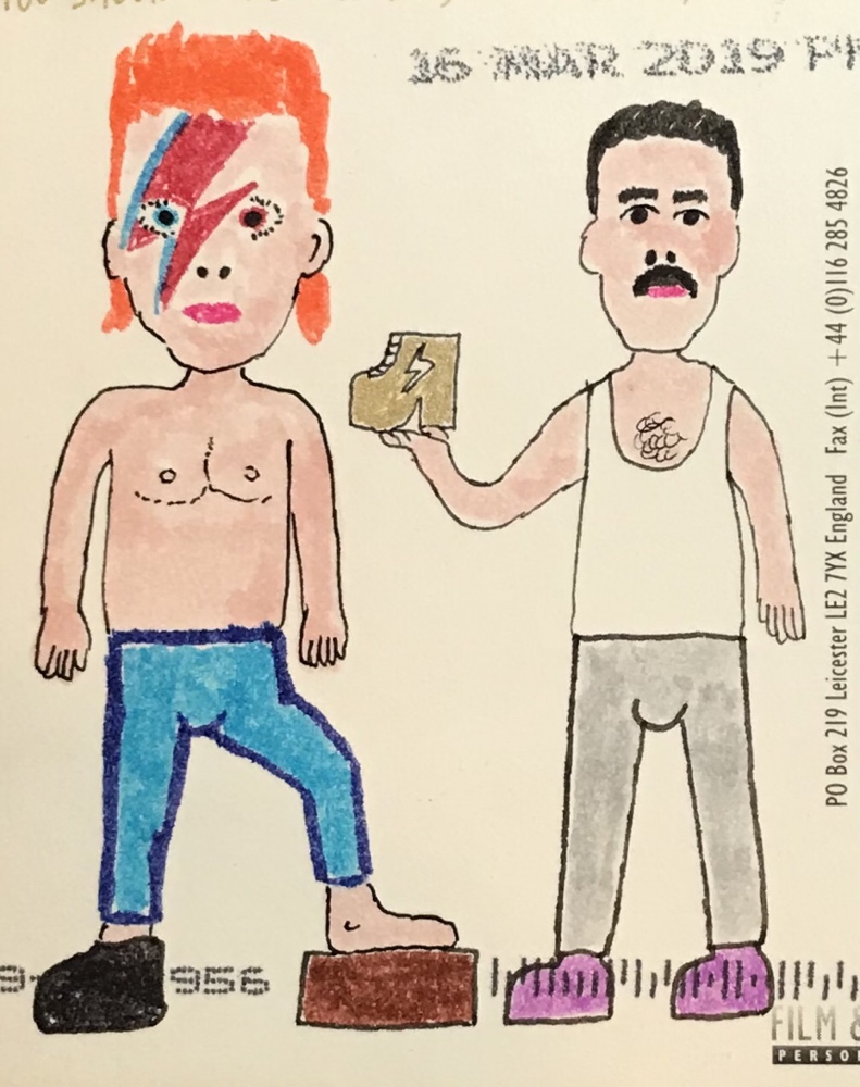
Of the cards themselves I love them all, but some have been particularly notable. I’ll feature two here, both Australian postcards but neither being sent from Australia! This one came from Germany:
And this one from Taiwan:
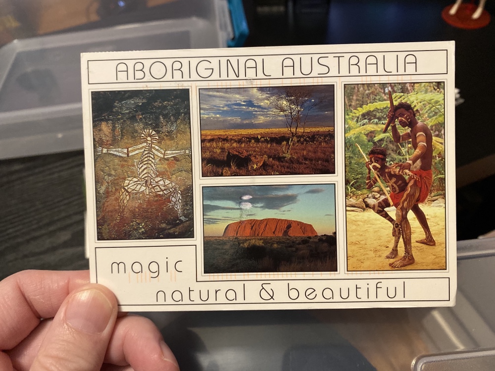
The latter is particularly great since the card itself is old – maybe 1980s – and I imagine she either found it in her parents collection or in a used bookstore! (And no, there’s no way people sending cards to me would know I am Australian which makes both of these even more amusing!)
These days I can send up to 11 cards at a time, and receive about 10 a month on average. At that rate I’ll get to 200 sometime around next August. Let’s hope at least some of those come from the Southern Hemisphere!