Category: Art

Stamp Otaku

I like postage stamps. Always have, always will. I still buy them a lot, especially when I’m in Australia. They are also one of the reasons I love sending postcards, and I enjoy sending (or receiving!) cards with exotic or particularly pretty stamps on them. I wonder if any of my recipients notice?

Screen Shot 2015-04-28 at 8.34.57 AM

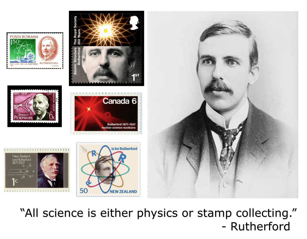
That’s a screen grab from yesterdays lecture, which was about the atomic structure. Rutherford is a real character, and I’ve always found it humorous that he’s been on so many postage stamps considering his (in)famous quote about science. Other slides in yesterdays lecture were peppered with stamps as well, and it’s actually quite easy to find stamps to use as illustrations in physics lectures.

In searching for such examples, I couldn’t help but notice that the masters of honoring their scientists on postage stamps are unquestionably the Germans. There are many and varied examples of beautiful stamps showcasing very famous scientists from German history.

Take for example this one:

stamp_hertz

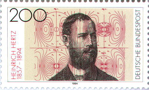
What a beautiful stamp! Hertz discovered electromagnetic waves, and this stamp displays the oscillations of the electric force due to a magnetic dipole (ie. EM waves) in the background. I love that the lines are superimposed over Hertz’s portrait, as if to put the science before the man.

index

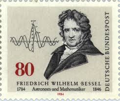
This stamp of Bessel is magnificent! The portrait is wonderful, and the fact the stamp prominently displays a plot of a ‘Bessel function’ (important mathematical tools required to solve complex partial differential equations) is just icing on the cake! How I’d love to stick this on a postcard!

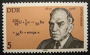
Here are some other wonderful examples of Germany’s science stamps:

4d739c481e91b5aba4d2cf071e453930

300px-Hahnfch

Stamps_of_Germany_(DDR)_1977,_MiNr_2215

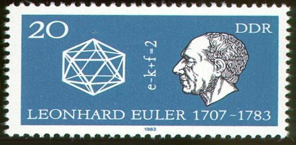
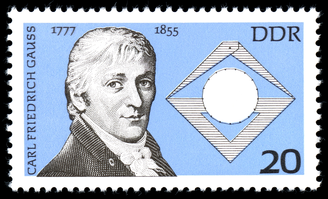
That last one (Gauss) is sublime! Gauss is one of the titans of mathematics, and is one of the few men to have multiple identities or equations named after him. One may imagine that they would have shown a Gaussian distribution on the stamp, but whoever designed it chose the 17-sided polygon that he created using compass and straightedge when he was only 19. I love it!

Lovely stamps these all are. The woodcut portraits add to the appeal, and the fact the stamps embrace the science only make them more appealing.

Of course Germany isn’t alone in recognizing science in their stamps. Here are a few other wonderful examples I found (and in some cases have inserted into lectures):

14444186-EGYPT-CIRCA-1995-stamp-printed-by-Egypt-shows-X-ray-of-hand-Wilhelm-Conrad-Rontgen-portrait-circa-19-Stock-Photo cbstamp stamp-fermi

bohr-stamp_1 Bulgaria 2947.300dpi

depositphotos_25194571-GREECE---CIRCA-1961-A-stamp-printed-in-Greece-from-the-Inauguration-of-Democritus-Nuclear-Research-Centre-Aghia-Paraskevi-issue-shows-ancient-Greek-philosopher-Democritus-circa-1961. article_schneider_phelan

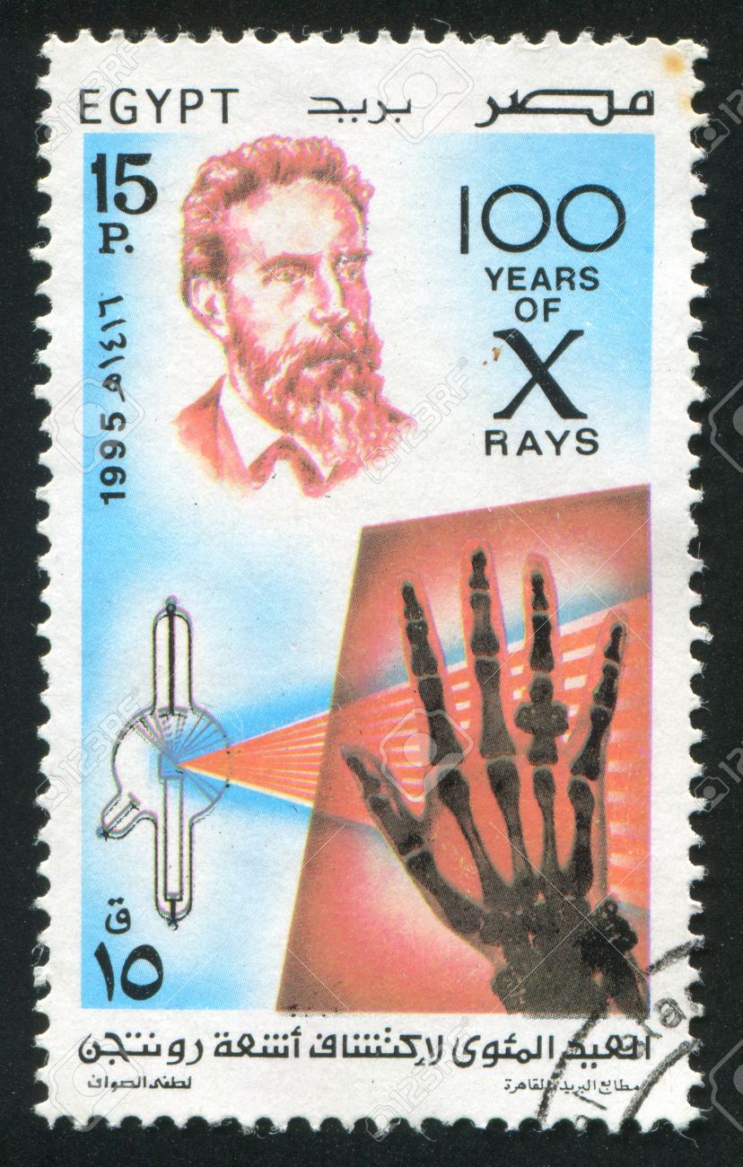
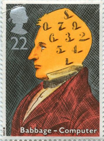
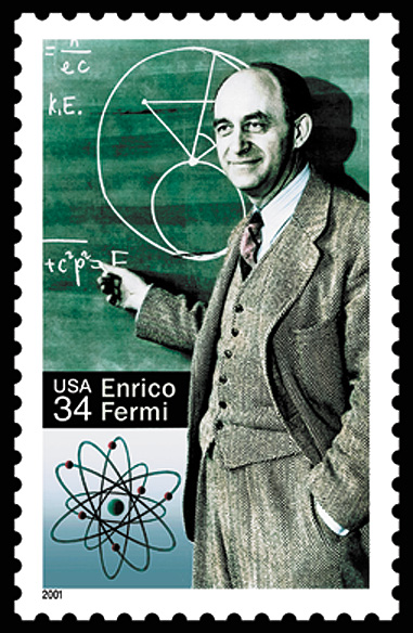
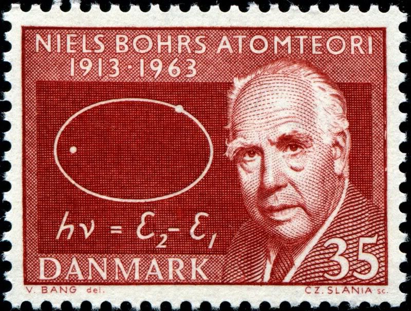
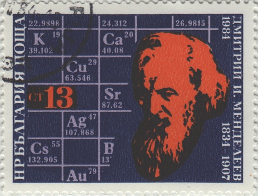
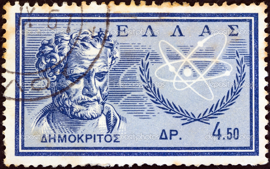
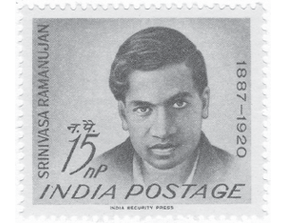
From the top, we have Roentgen (x-ray), Babbage (computers), Fermi (atomic physics), Bohr (atomic structure), Mendelev (chemistry), Democritus (coined the word ‘atom’ in 450BC) and Ramanujan (Indian mathematics prodigy). I love them all. I wish I had them all in a big frame. I’d display it proudly in my office.

You’re all wondering “What about Einstein?” He’s on more stamps than any other scientist, and they run the entire range of design and theme, since his fame moved into celebrity as well. I think this is perhaps my favourite Einstein stamp of all those I found:

stamp-italy-centenary-of-albert-einstein-1979

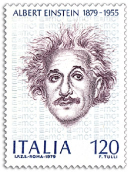
It’s simple, subtle (note the background) and a lovely portrait of Einstein when he wasn’t much older than when he presented his most important theories. This stamp would look beautiful on the back of a postcard of a surfing koala or kangaroo drinking a beer 😉

Strandbeest Rhino

At the risk of turning this blog into a “look what model kit I made this week” list… I got this curious thing for my birthday the other week:

IMG_6526

It’s a model of a ‘Strandbeest’, which is a type of wind-propelled walking sculpture made by Dutch artist Theo Jansen. You can read more about his creations here. His ‘beests’ are massive and insanely complex, but this model kit reproduces a smaller version of one of them using the same principles.

Here’s what it looked like before assembly:

IMG_6528 IMG_6527

Everything looked clean and relatively simple; a nice departure from some other kits I have made recently.

IMG_6529 IMG_6530

Assembly was very quick. Each of the twelve legs have only 6 pieces that snapped together tightly with very little effort. The instructions are very clear, the pieces easy to remove from the runners and everything fits together perfectly. This is a very well engineered kit.

IMG_6531

That’s a shot of the first two legs showing the crankshaft and drive-rod mechanism. It’s very clever how everything fits together and still has a very large range of movement.

IMG_6533

That’s six legs attached. One half of the kit is complete!

IMG_6536

And there’s the finished guy! In theory, when wind turns the fan propeller on the top, a gearing mechanism will turn the crank shaft and make it walk along. It’s complex but very simple mechanically, and it only took about an hour  to assemble (with no glue or tools). But does it walk…?

Here’s the proof:

Not bad is it!

The actual rhino strandbeest was much bigger and could actually carry people inside. It weighed 3.2 tonnes, and is now a permanent (immobile) sculpture in a pond in Amsterdam. Here’s a photo that was taken the day it walked on an abandoned runway in the Netherlands:

strandbeest03

As it turns out I actually received two (different) strandbeest kits for my birthday. I think the other one will patiently wait for a while 🙂

The Nixie Clock

nnn

Nixie tubes were invented in 1955 and were a popular pre-digital form of displaying numerals in electronic circuits. They use a technology somewhat similar to neon lights, and are designed so the shape of the discharge corresponds to numbers (or rarely letters). They were obsoleted in the 1970s by LCD displays, and even more so in the 1980s by pixel displays.

But they have experienced a bit of a resurgence in recent years since they are so pretty, and so retro. It is a great regret of mine that several years ago, while cleaning out old lab equipment at school, I discarded a (broken) nixie geiger counter from the 1960s. I should have kept it, and fixed it!

And then this year, for my birthday, KLS purchased me a Nixie clock do-it-yourself kit. I made it this past week, and it was easily the most challenging kit of any kind that I have ever made.

IMG_6440

It starts with the above – many components, an empty printed circuit board (PCB) and a whole lot of fitting and soldering to be done. Now I’m not the biggest fan of soldering, and despite once being paid to teach others how to do it (hi Florence!) I don’t consider myself very good. But I borrowed an iron from school, prepared a comfortable work surface and started…

IMG_6446

That’s about 3 or 4 hours later. Most of the resistors are in place, as well as the diodes and all the capacitors. I believe, at this point, I had soldered over 170 connections. It turned out to be easier than I thought, but at the same time very detailed work. If I didn’t have any experience at all, it would have been almost impossible to do it correctly due to how close some connections were.

The hardest thing to this point was actually preparing the nixie mounts. This photo shows the process:

IMG_6445

The circular bakelite discs had to have the conductive pins pushed into them and then the whole thing was soldered to the PCB. The difficulty was the pins were molded inside plastic and you had to break them out. This was much harder than it should have been and I cut myself more than once. It was frustrating but I got it done.

The next step was to add the LEDs:

IMG_6449

Then a few more components (including the chips) before testing to see if everything had been done correctly:

IMG_6455

The relief I felt at this point was incredible. This was during the second day of assembly, after a half dozen hours or so. I’d been frustrated up and down by this point since the ‘instructions’ for the kit consisted of a series of forums posts on a website that were lacking (in my opinion) in certain pieces of information that would have made things much easier had I known them in advance.

But I was half way through the PCB assembly and it was working (the LEDs were lit and the current was ~20 mA). Here’s the back of the kit at this point:

IMG_6452

The next step was to add the nixies, as well as the other essential components to actually make it a clock (motion sensors, crystal, battery backup etc.). Here’s one of the nixies:

IMG_6463

The kit comes with five in total: four numeric and one symbolic (+,-.>.<). Putting the 13 leads into the sockets on the PCB was easily the hardest and most frustrating part of the entire kit, and took about an hour in total for all five. Here we are mid-process:

IMG_6464

And when it was done – time to test it all:

IMG_6466

OMG it works! I was super relieved here – everything lit up as it should have and the whole thing seemed to work. Little did I know I still had a lot ahead of me.

Next I had to start building the case. Unfortunately two pieces were received broken, and a third was miscut. The case as a whole was poorly designed, and the pieces didn’t fit together anywhere near as good as I feel they should have. I had to do a lot of sanding and drilling to get things looking acceptable (but as you see later, believe I mostly succeeded). Again, a complete beginner would have been in trouble in this step. Here’s a shot mid case assembly:

IMG_6468

The five blue LEDs are asthetic, and you can see in the photo two above that they are all on (under the nixies). That was the last photo taken of them on, because for reasons unknown after I soldered the final component (the backup capacitor battery) and put it in the case the middle LED stopped working. Here’s a photo of the clock – all wiring completed – showing this (the case is not yet complete):

IMG_6469

In the front, just to the left of one of the chips, you can see a black LED. Right behind that (slightly up left) is a sensor chip. These two parts are required to set the clock, which uses a virtual motion controlled ‘air switch’ to set features like time, date, 24-hour mode, alarm etc. It’s a remarkably full-featured clock, but mine had a big problem: the motion sensor barely works.

It took me endless trial-and-error to get the switch working, entailing making IR blocks out of black-colored paper and moving my hand around like a deranged puppet for about an hour trying to control the ultra-unresponsive switch. Countless times during this process I lamented the fact the designer didn’t just choose to add buttons. But eventually I got the time set, and now – five days later – the clock continues to keep perfect time.

Here’s a shot of my completed clock:

IMG_6500

I think I did very well in hiding the breaks in the case, and I think the middle LED being burned out is mostly unnoticeable. In fact I think it looks very nice, and certainly is very striking in our entertainment center under the TV where it glows impressively in the dark.

IMG_6478

The nixies are very, very pretty aren’t they. This shot is with the cover (of the case) of, and you can see a piece of blackened paper I have resting over the sensor to prevent it from flaking out again. The clock is permanently set to 24 hour time, and the middle nixie alternates between – and + every second. It’s quite lovely.

It was an extremely difficult and frustrating kit to build, and I don’t think it’s probably worth what it cost. But I did my very best, and it works and looks quite good, so in the end I’m quite happy with my new nixie clock 🙂