Time for more chicken ramen!
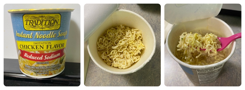
Tradition Instant Noodle Soup Chicken Flavor Reduced Sodium (290 Calories, 14 g fat, 730 mg sodium)
Yet another product from this company, and as best I can tell virtually identical to the non sodium free version, which I gave a score of 0/10. So how does this stack up? Well, it’s even worse! The other had woeful noodles and no flavor at all (I even thought they’d forgotten the flavor packet), and this one has even less. It’s barely edible: -1/10
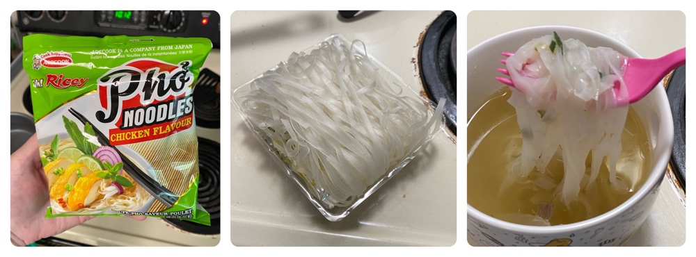
Oh Ricey! Pho Noodles Chicken Flavor (270 Calories, 6 g fat, 1600 mg sodium)
I’m bending the rules here a bit since these aren’t ramen, but since they’re a dehydrated brick noodle product I doubt anyone will complain. This is a rice noodle soup, with unusual translucent noodles that secreted a frankly disturbing slime when heated. The flavor pack is just a bag of sticky oil and the entire concoction, once prepared, was about as appetizing as something I’d award a score of 0/10.
Despite my reaction to this dross, KLS ate it. I just now asked her what she thought and she said “I don’t remember it!”
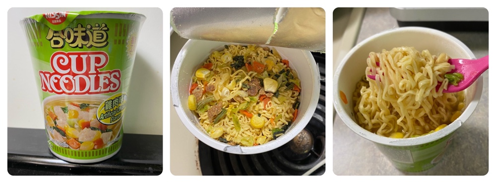
Cup Noodle Artificial Chicken Flavor (320 Calories, 11 g fat, 1620 mg sodium)
I can barely believe I haven’t yet covered a Cup Noodle ramen yet, especially since I even bought a model kit of one!
This is a Chinese version and I assumed it’s probably the same as the USA one. After trying it though, I’m doubtful. The noodles are good (as you would expect from the guys who invented cup ramen) but the taste was far too earthy for my delicate palette, and even had a hint of spiciness. Overall I think this is a good product, just probably not to my taste: 6/10.
Nine installments of ramen reviews so far, and there’s more to come! Stay tuned…