I got a postcard the other day with a kiwi stamp on it. On the back, next to the sketch of the extinct ‘kiwi squid’, was the following request: “Please blog a Christmas wish list!”
I think we know who sent it, so here goes.
Video Game Section
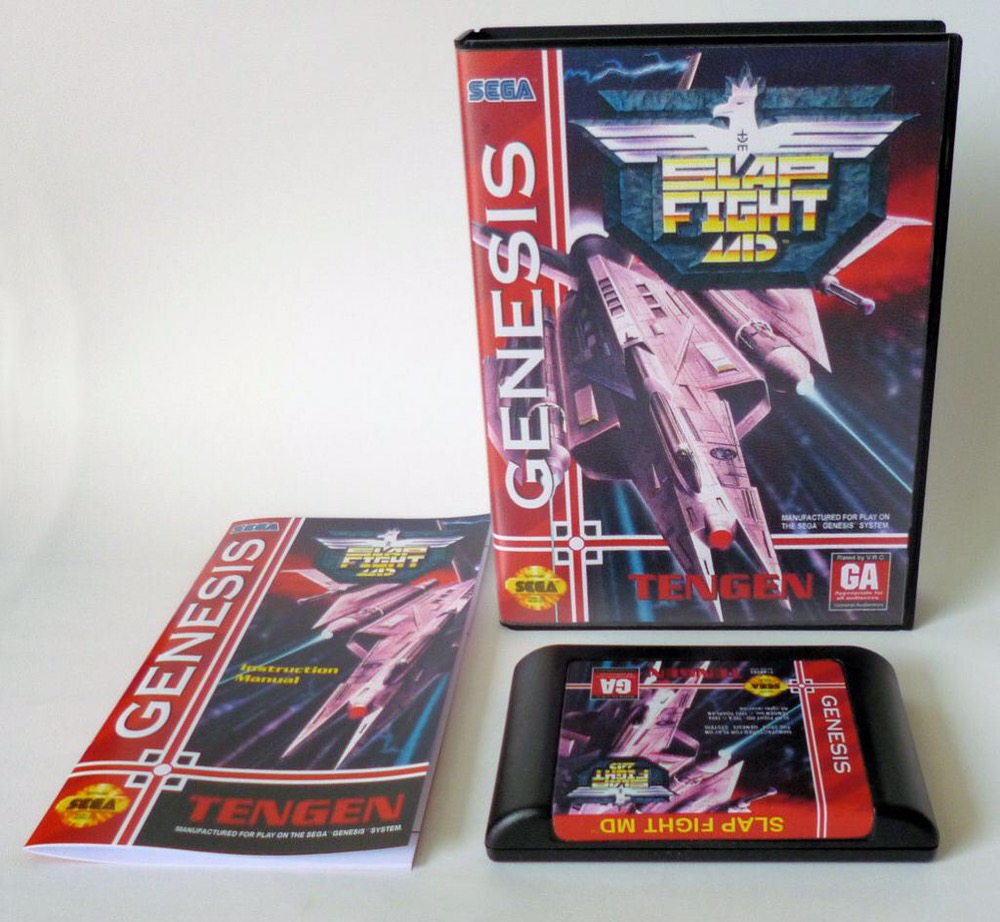
Slap Fight for the Megadrive is pretty high on my list, but – as with most Genesis shooters – is a real dog to find (boxed with manual of course). It’s a mostly forgotten game these days but I always loved it. Bernard may be able to use his contacts to obtain this, but he’ll weep quietly when he sees the price (>$350) so may want to consider this only-slightly-less-expensive alternate:
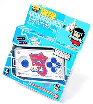
Taito Nostalgia 2 is a plug-and-play TV game, which includes a remixed Slap Fight amongst its handful of games. This is a 10 year old JP-only release and may be ‘challenging’ to find at a reasonable price 🙂
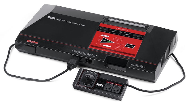
That’s a Sega Master System, an obsolete 8-bit system I’ve been getting more and more interested in. They’re not too difficult to find, and not prohibitively expensive, but of course they are nothing without games to play. And here’s where things get a bit chancey. Because if he gets me one of these, he’d have to get me some games as well.
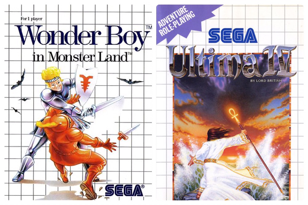
These two are a good start. Other good options include Sagaia, Zillion, Master Of Darkness, Phantasie Star etc. Very likely each of these games will cost more than the system!
Speaking of games…
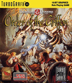
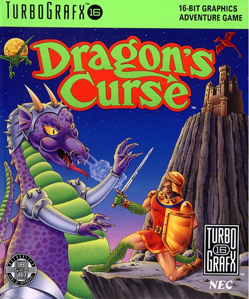
Bernard’s going to need the devil’s luck finding these two TG-16 games (boxed of course), and then open his wallet wide to get them for me…
RPG Section
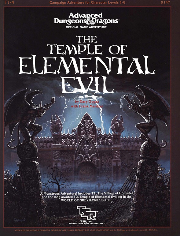
This AD&D module was published a startling 31 years ago and is a legendary classic. It’s also bloody expensive and rarely complete (the complete boxed set has oodles of maps and handouts in it). I almost bought it myself about 25 years ago but chose not to knowing that in 2016 my brother would get it for me.

This is apparently a mostly stupid expansion to D&D that was put out in 1986 to keep stubborn gamers who hadn’t moved on to AD&D busy. I’ve always been intrigued but it’s bloody hard to find complete. And sticker-shockingly pricey. Thanks Bernard.
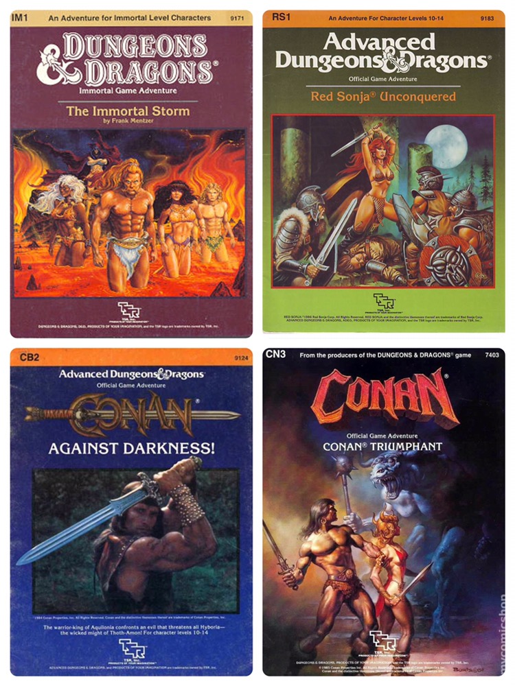
With a bit of effort, sacrifice and prayer Bernard should be able to get me one of these AD&D manuals for under a Benjamin. The Conan ones are apparently very short (one is only 12 pages I think) which means the cost/page is sky-high. Good thing Bernard spares no expense!
Toy Section
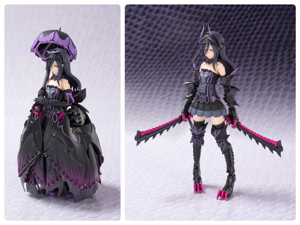
Gore Magala Girl just came out. As in last week. It would be challenging get it before Xmas to say the least, plus it’s expensive; more than I’ve ever paid for any figure. I’m putting it here mostly to show it off since you can bet I’m buying it the second I get back from Oz. In other words this was originally added as a sincere list item, but like the ZOID from 2014 I’ve now retracted it to buy it for myself 🙂
Computer Section
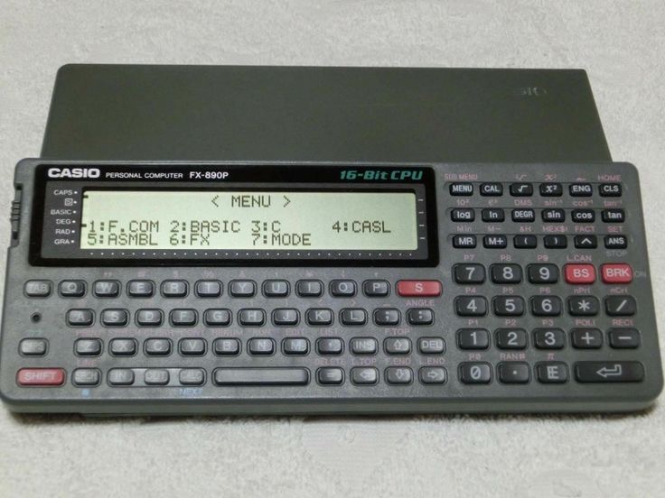
That’s a Casio FX 890P handheld computer, which (apparently) has several built-in languages. Just the machine for me to write the next (long awaited) Mercenary King game on. I’m putting any generic programmable handheld computer on this list, so Bernard can surprise me!
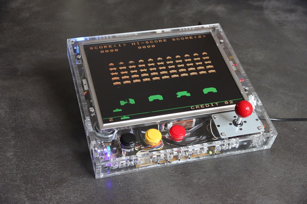
That’s a RetroPie handheld. It’s a lovely handheld MAME device based around a Raspberry Pi. Now I have conflicting feelings about emulation, especially of consoles, and frankly couldn’t be bothered setting up a Pi or (even less so) downloading MAME roms. But Bernard will do it all for me, because Christmas 🙂
Trading Card Section
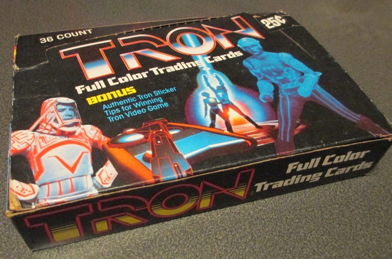
Get me this and I promise you’ll get Tron stickers on postcards 🙂
MTG Section
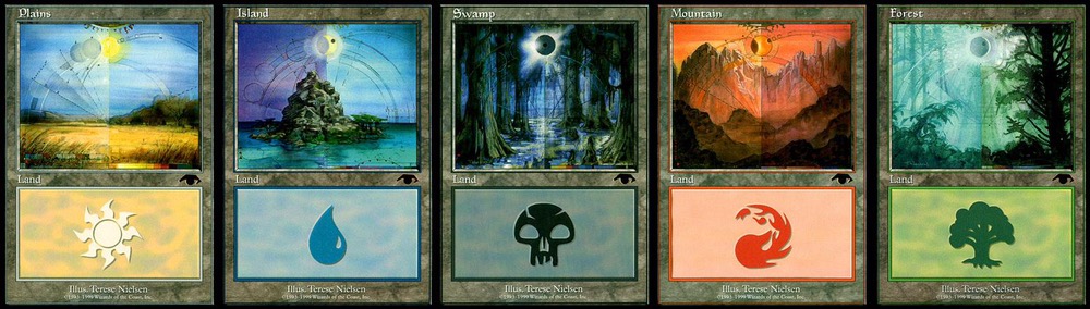
My MTG basic land collection is pretty massive now and almost complete. But I don’t have any of the five stupidly rare and expensive ‘guru’ lands. If Bernards got about $2000+ lying around, he’ll get me these 5 cards for Christmas!
‘There’s only two weeks and this list is insane!’ Section
– Any Gundam kit
– A t-shirt (size L)
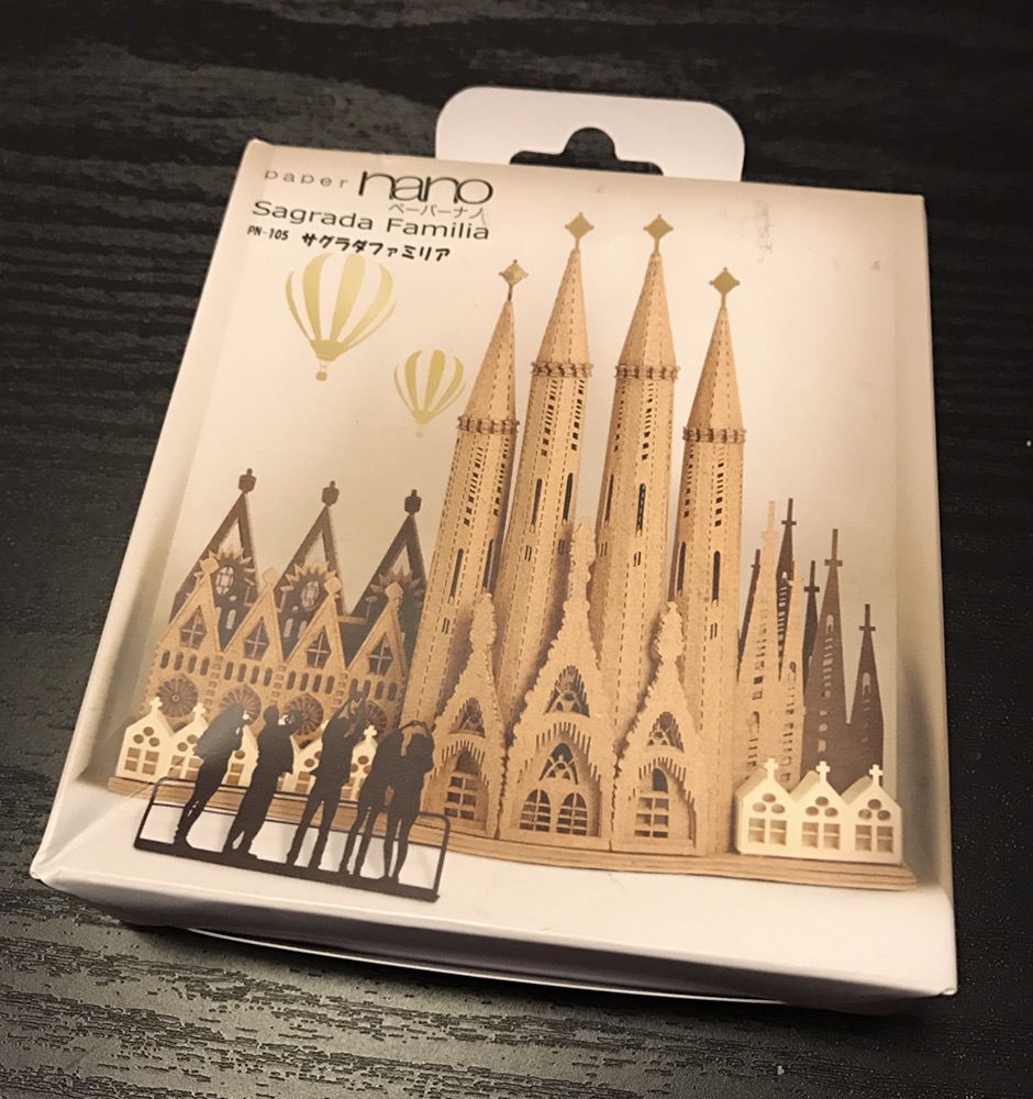
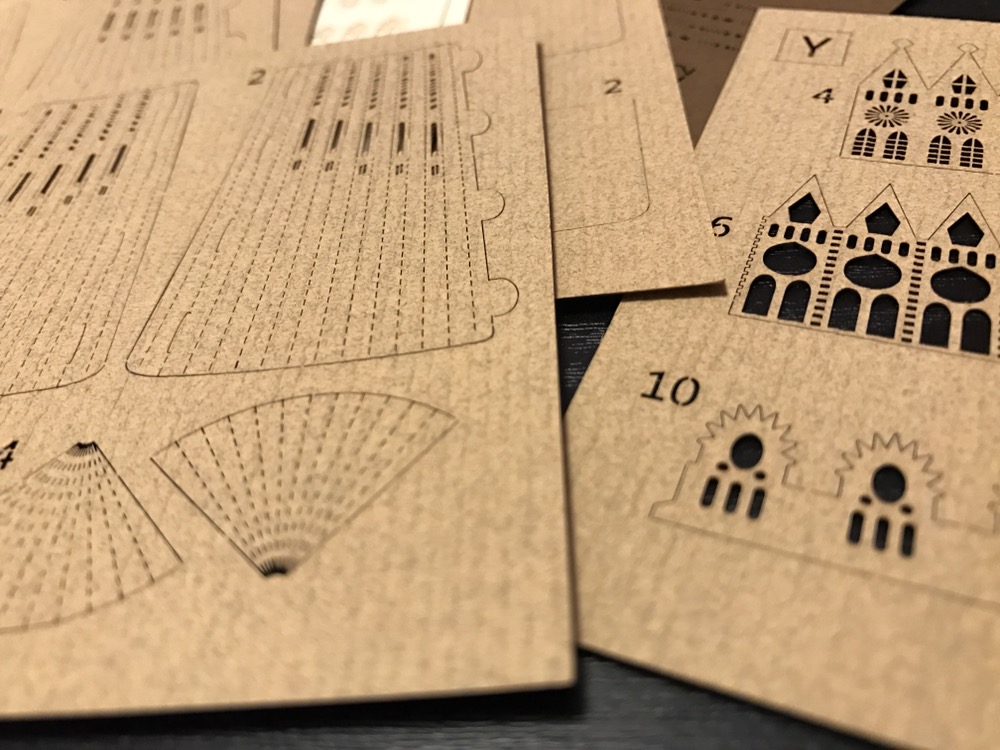
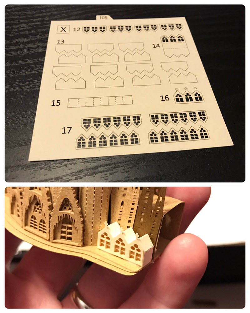
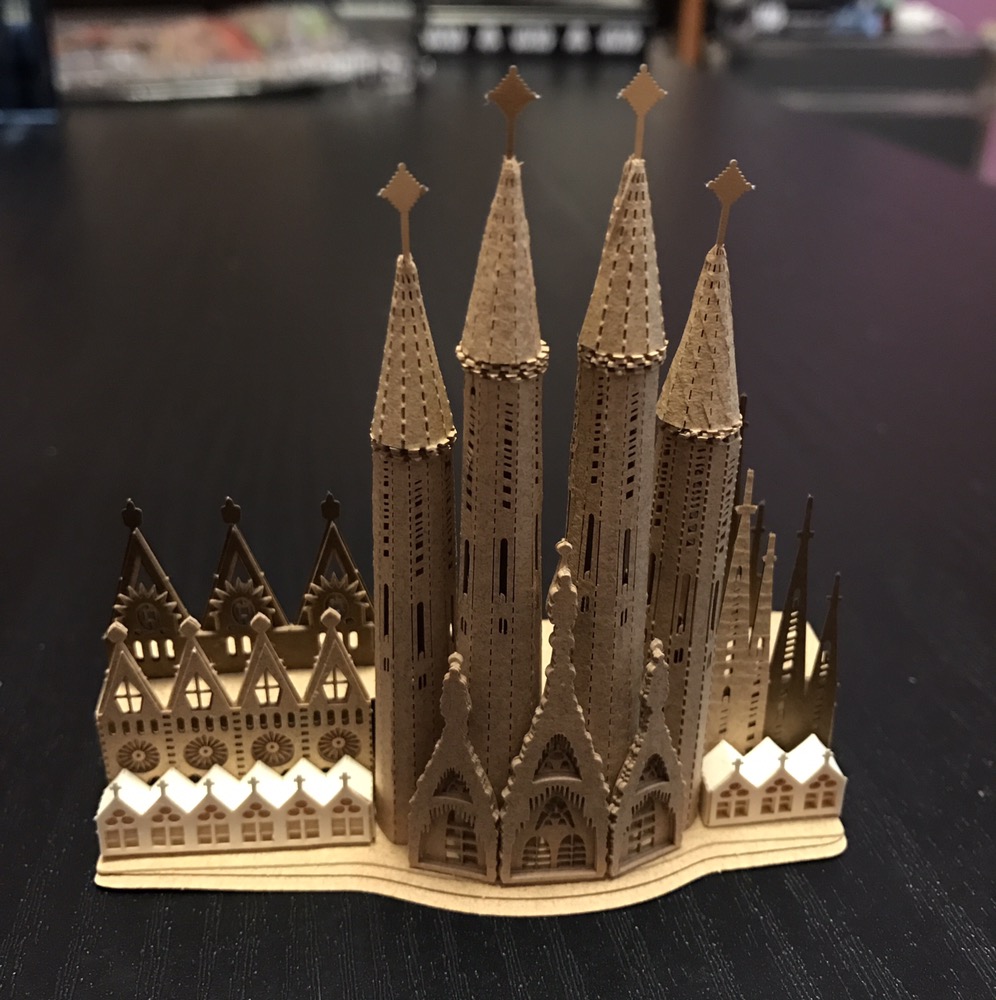
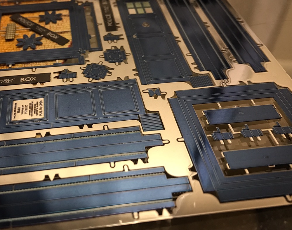
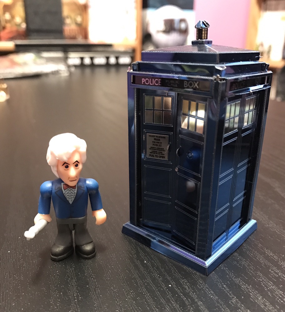
– An interesting jigsaw (suitable for framing)
– Any gamebook I don’t own (check the list on your network)
– No metal miniatures 🙂
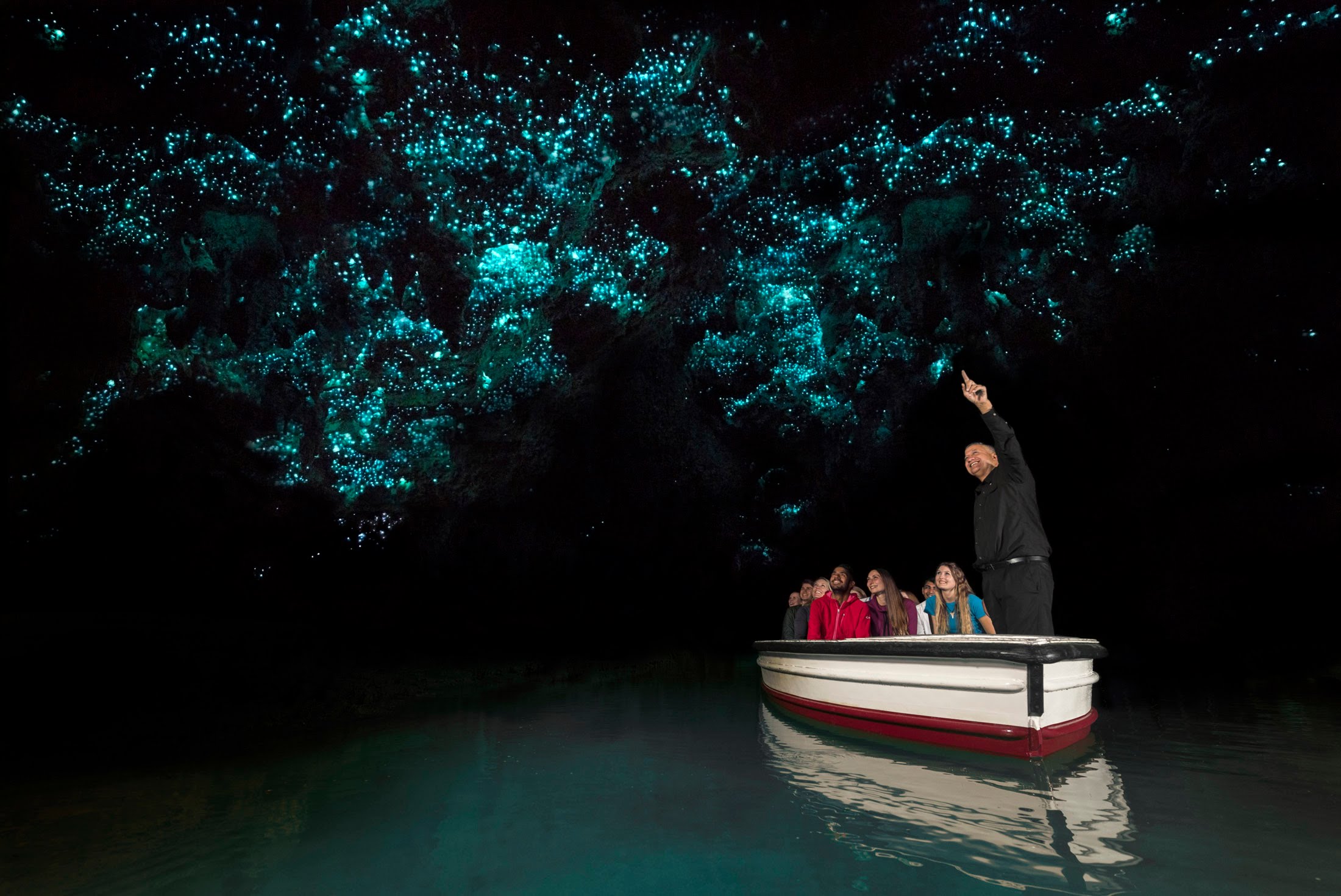
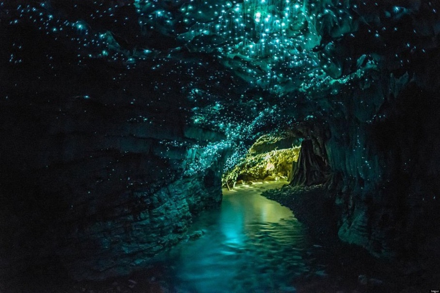
– Glowworm stamps!