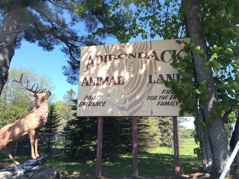
We recently learned of an animal park about an hours drive from here and yesterday went to check it out.

This is a family run animal park over about 100 acres with many types of animal on display and a safari ride. How did we never know it existed?
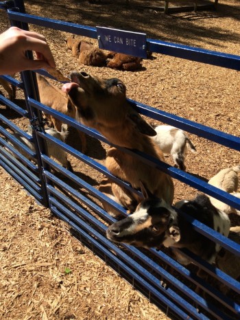
Unlike almost every other park/zoo I’ve been to, you can buy food (ryvita biscuits actually) and feed virtually every single animal. Since most of them are ‘horsey things’ and happily chow down on the biscuits, this means you can get quite close to most of the beasts on display. We gave food to deer, llama, alpaca, goats, giraffes, kangaroos (!), zebra, monkeys and even a wolf!
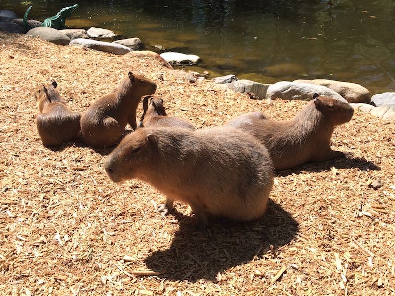
And these guys…
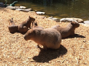
The capybara family! We knew they had capybara before we visited but were surprised by the fact they had a whole family in such a large enclosure. Mum and dad and the three babies were incredibly adorable and we spent a great while admiring them. To her delight, KLS was actually able to entice the placid mother over for a snack:
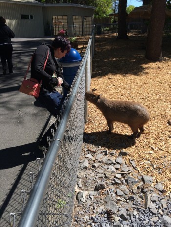
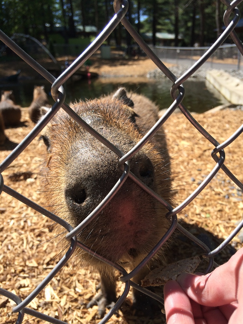
Here’s her charming face up close:

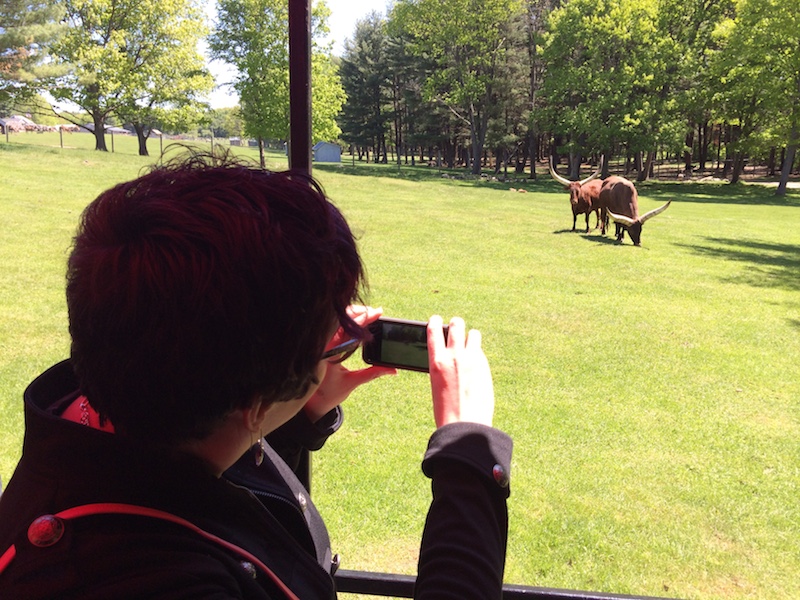
The safari ride was a highlight. Although not particularly long, it was very well done (especially the narration) and since we went on the first one of the day the animals were all active and very interested in us:
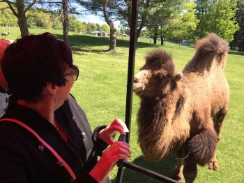

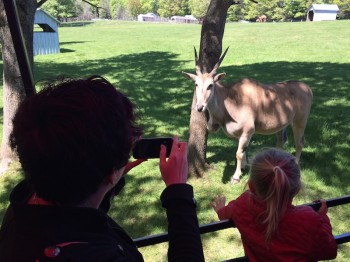
The camel in the first shot is apparently one of the four biggest in the US, standing almost 9 feet in height! The safari had camels (one and two humps), bison, rhea, goats, pigs, ostriches, several types of antelope and probably a few other things I am forgetting. There were quite a few newborn babies and many eggs in nests. Apparently breeding came early this year due to the unseasonably warm weather we had a few weeks ago.
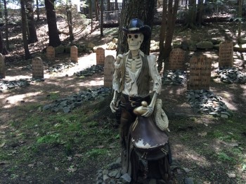
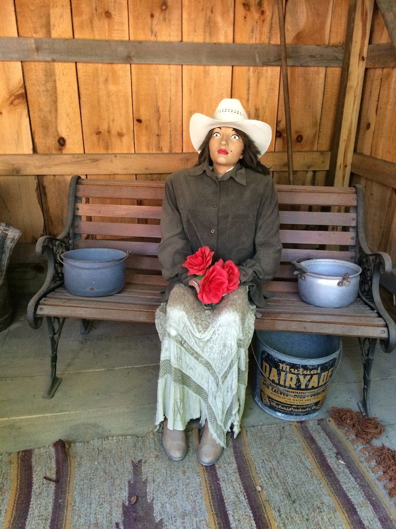
There were some weird elements to the park. Displays such as the above are common in some of these family run attractions here in the US, and this one was part of a ‘western village’ that included similar things like this…

And this…
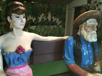
It was all weird and creepy, and very, very dated. The mystery is we couldn’t quite work out when it had been built or why it still existed (although to be honest, the many kids there yesterday seemed to love it all). The age of the park in general we couldn’t determine, and there doesn’t seem to be any history online including on their own site. Had I know this yesterday, I would have asked someone.
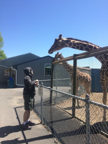
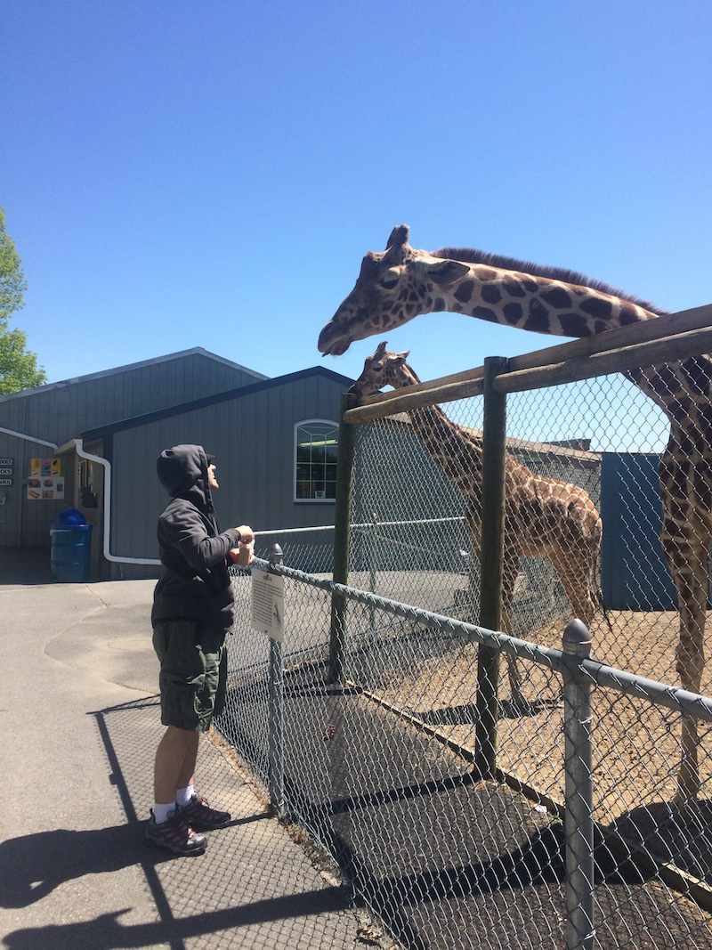
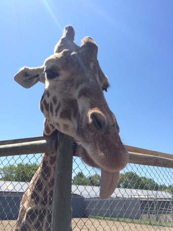
I was surprised they had giraffes. The enclosure was a bit grim, but it opened out onto the safari so I assume they let them wander around when not on display. As with many of the animals, they happily accepted a ryvita biscuit (or ten) from us:
It’s not a massive park, and it took us about 3 hours to see everything they had (and feed almost all of them!). We enjoyed the place quite a bit and are glad we went.