The drive north saw the busiest roads we’ve yet encountered as we drove through Ulladulla, Bewong and Nowra. Eventually we reached our destination: Wollongong.
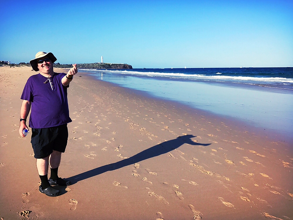
I spent several days here with Adam a few years back, but this is Bernard’s first time. The sun was high and hot as we explored the CBD and higher and hotter still at the beach.
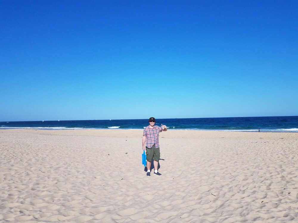
Neither of us had sunblock on. You’d think after running out the day before we’d have thought to bought some, especially considering we’d discussed exactly this standing outside a store. But we didn’t, and therefore didn’t use any, and somehow didn’t burn.
Use sunblock kids. Don’t be fools like us!
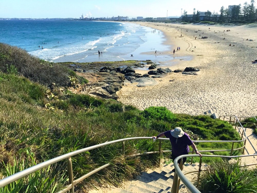
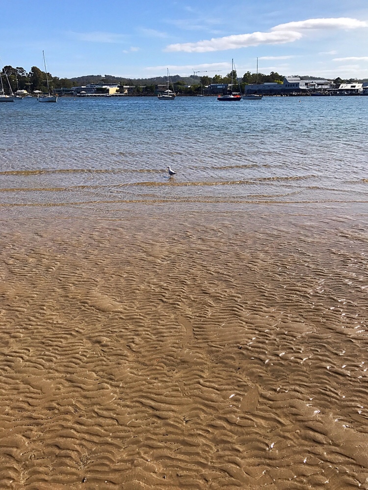
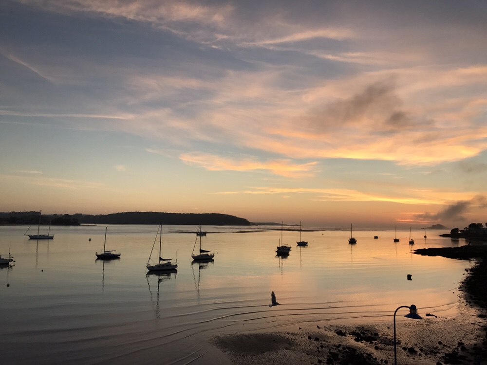
We walked a long way on that beach; all the way to the lighthouse you see in the first photo. Then we walked back to the hotel. We walked a lot yesterday, and it’s probably not surprising I woke tired!
Today – Bernard’s birthday! – we drive the last leg of this road trip all the way to Newcastle where a certain pair are expecting us…