Sega released their Game Gear handheld console in 1990 as their answer to Nintendo’s Gameboy. It was marketed heavily on the strength of its full colour backlit screen, but poor software support coupled with the market dominance of the Gameboy led to the Game Gear never becoming a true hit.
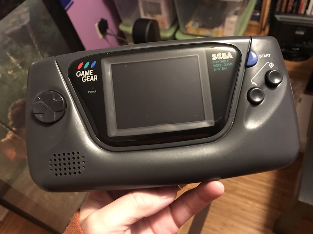
This is my Game Gear. I never bought the system myself – I wasn’t interested in any of its games – but JAF (ie. KLS’s mum) bought herself one. Specifically on June 27, 1993 for $129.99. I know this because I still have the receipt, which shows the rechargeable battery pack ($49.99) and ‘Super Wide Gear’ magnifier ($29.99) were bought at the same time.
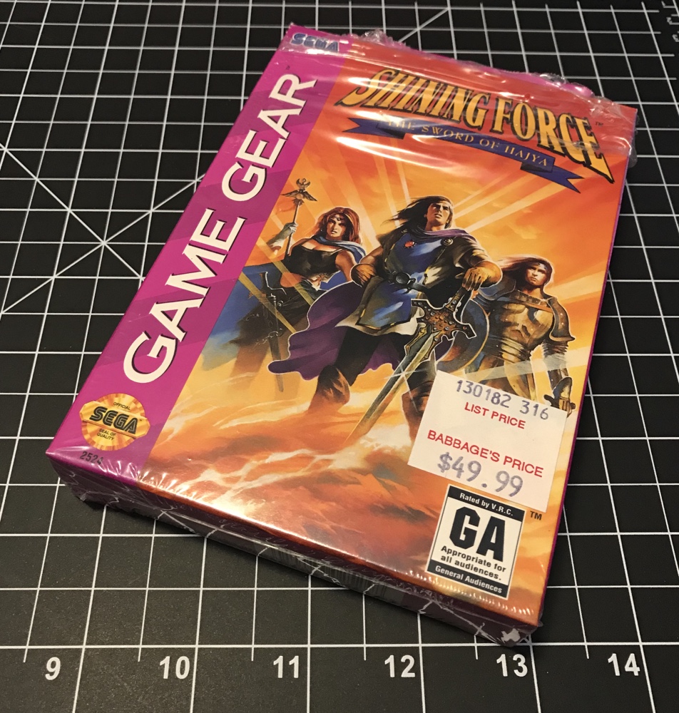
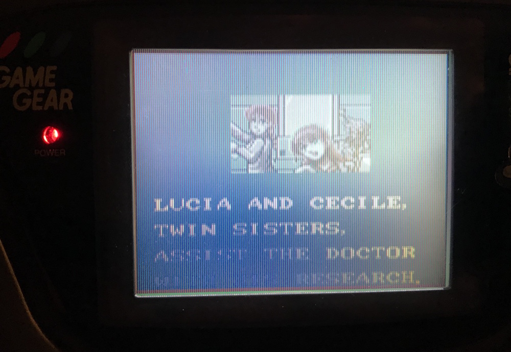
Joyce would eventually bequeath the system to me along with the few games she had bought. I myself had bought one game (shown above) but when I inherited it in 1994 I put it into storage and essentially ignored it for 24 years.
Then last year in Scotland I found a large collection of Game Gear games being sold at a CEX used game store and bought them all! Eighteen games in total cost me £18, which was a steal even considering they were unboxed. I was eager to try them, and when I returned to the USA I powered the system up for the first time in decades and saw this:
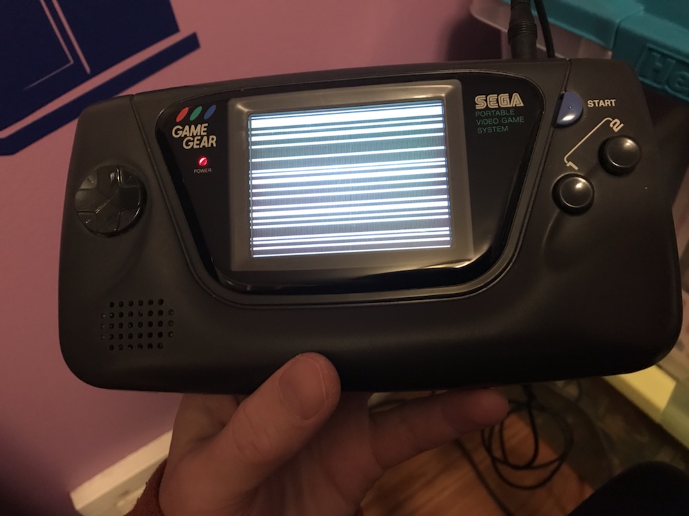
Yes it had broken and the screen just displayed garbage. There were sound problems as well. I wasn’t particularly surprised by this because in the decades since release the Game Gear has become infamous for the lousy quality that Sega chose to cut costs. Many components are second-rate, and the capacitors in particular are known to be the worst ever placed in a game console.
In short, all the capacitors (about 30) needed to be replaced. I bought tools and a capacitor kit, then did nothing for four months! This was because I knew it wasn’t going to be easy at all (leaky surface mounted capacitors needed to be replaced with wired ones) and because the cost of paying someone to do it was cheaper than my time. Eventually that’s what I did, and $30 and one month of work later my Game Gear was fixed.
Now it works we can see the other flaw. The much-marketed full colour screen? It’s terrible! Very washed out, with a slow refresh rate and very limited viewing angle it makes playing anything a bit of a chore in the day of OLED invisible pixel displays!
In short: all games look bad on it, and don’t even have the retro appeal of (for instance) a Gameboy.
Things are slightly better using the magnifier, even if it does make the system less portable. It also reduces the viewing angle quite notably, so you’re better off putting it on a table if you want to use it.
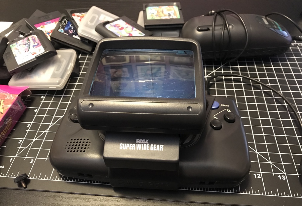
Let’s not discuss the absurd battery pack (top left in the above photo), which gives only about an hours battery life at the expense of a heavy eggplant-sized unit that clips onto your belt. Less expensive I suppose than 6 AA batteries every three hours, but once again something that makes us question how portable this system actually was?
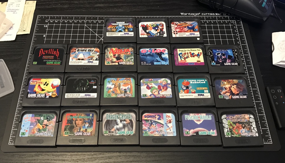
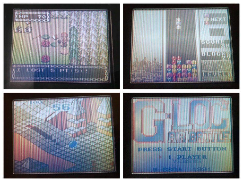
The above is most of my library. I forgot to take a game out of the system (Columns) and of course Shining Force isn’t included. Game Gear games aren’t particularly valuable compared to other handhelds, mostly because if you’re interested in playing them you’ll almost always be emulating. The most valuable game in my collection (Shining Force) is ‘worth’ only about what I paid for it 25 years ago.
This system is a curiosity these days. It had very few good games at the time, and almost none worth seriously playing today. The systems themselves are unreliable, and even when repaired are frustrating to use unless you spent too much to replace the screen with an LED upgrade. This is very much a system just for my collection, and I reckon it could be decades before I turn it on again…