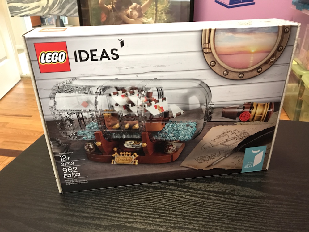
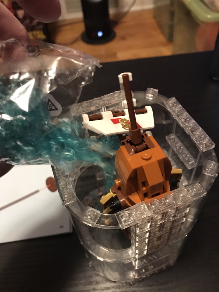
This kit was immensely fun to build and looks incredible. I hope LEGO has more innovative ideas like this in the future!
“Life In The So-Called Space Age”
This kit was immensely fun to build and looks incredible. I hope LEGO has more innovative ideas like this in the future!
I arrived in Sydney yesterday by train, and after checking in to an extraordinary hotel room wasted no time seeing the tourist sites.
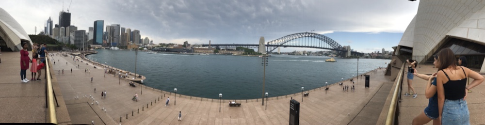

I walked from Central to Darling Harbour to Circular Quay and back – some 30k steps – and by the time I crashed in my room after dark I was ruined ?
This morning I was up bright and early to pack, before heading to the Star Wars Identities exhibit at the Powerhouse Museum.
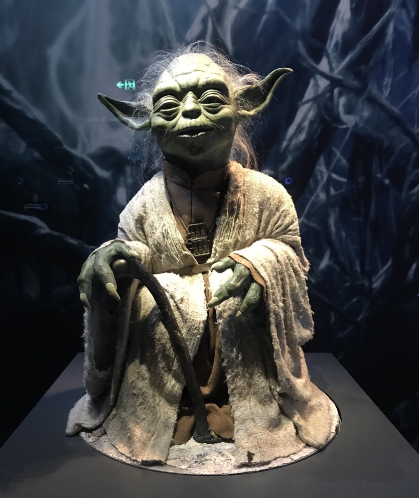
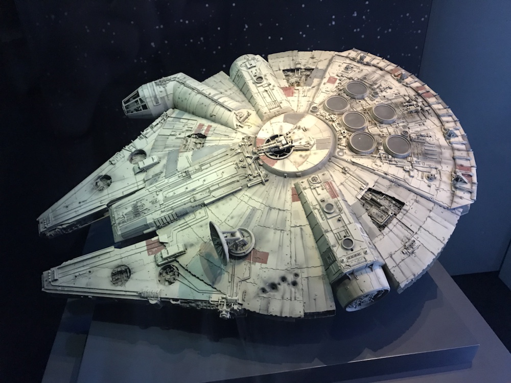
This is a remarkable exhibit of original props, costumes, models etc from the entire Star Wars saga (including Clone Wars). It is beautifully presented and it was magical to be so close to iconic items like the Millennium Falcon model actually used in Empire:
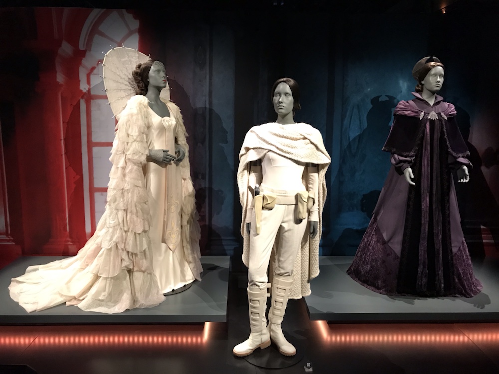
Or costumes worn by most of the major characters:
In addition, via interactive stations throughout the exhibit you create your very own Star Wars character!
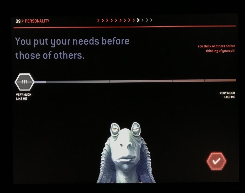
I suppose the idea is to reproduce yourself in Star Wars firm, but I found myself compelled to spawn a uniquely original creation. Dear readers, I present my own Star Wars creation, Gab Frogger:
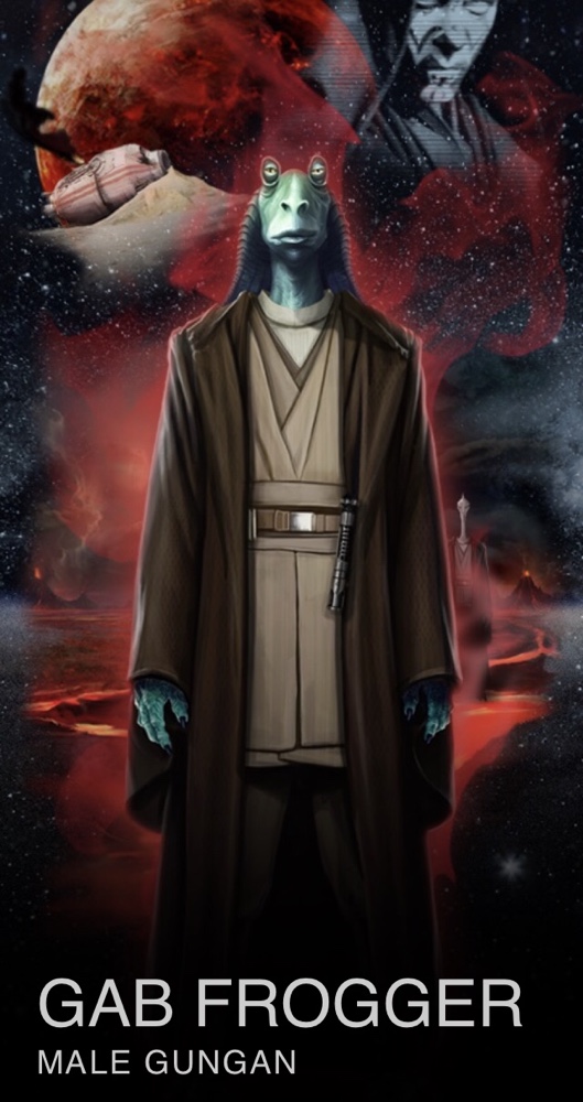
The name was my creation, and I’ll humbly suggest it’s much better than what others used (I saw an Ewok pilot named Brendan). Here’s Gab’s bio:

As with all Gungans, Gab is immediately endearing despite his dark side tendencies, and I’ve grown to love the froggy scamp already. I hope he turns up in Episode IX!
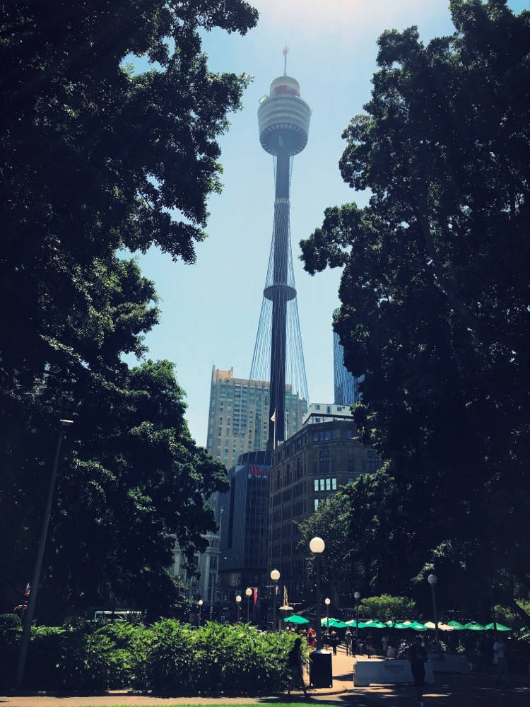
That’s Sydney Tower, which has stood since 1981 in the center of the city. I’ve been up several times but not in quite a few years and figured it was time once again.
Admission includes a surprisingly good (but short) 3D film which you watch before going up. I’m not quite sure why it even exists since it has almost nothing to do with the tower but I imagine the purpose was originally line-management which is redundant now since the tower doesn’t seem too popular.
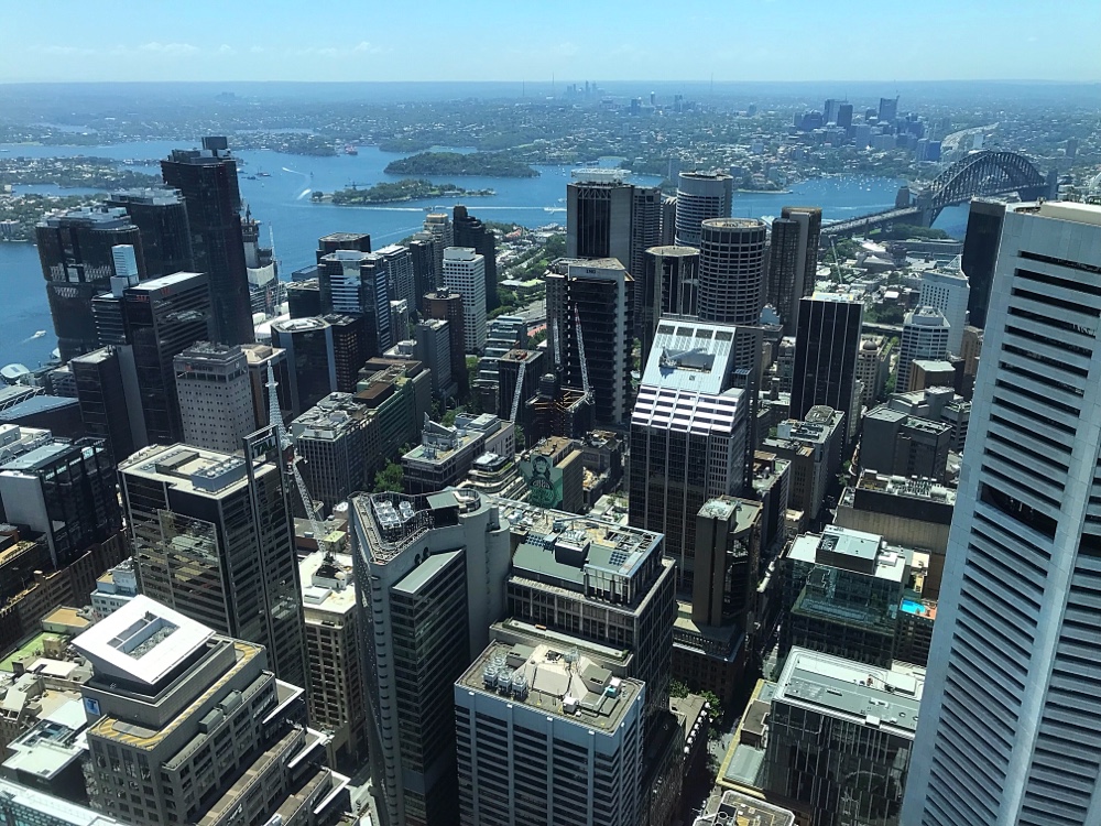
But it was good! Today was sunny and clear and I could see forever. It wasn’t busy up top and I spent much longer than I’d expected up there. If you like observation towers, this is probably worth it at the slightly elevated price.

This will be my last post from Oz this trip, as early tomorrow I head to the airport for Tokyo where I’ll meet Bernard for the next 8 days! Stay tuned for our eastern adventures…
A few months back I got one of these:
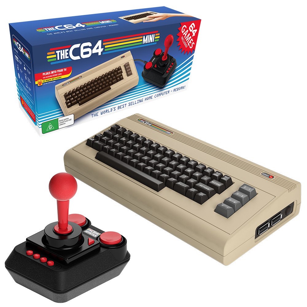
It’s the C64 Mini console, which is a Commodore 64 on-a-chip in a cute little case with a bunch of software built in.
It’s good but not great, slightly crippled by a poor joystick and input lag. It’s also disappointingly bare bones in terms of presentation, with the lack of instructions making many of the games – originally from the 80s – borderline unplayably difficult.
But none of this matters since it includes C64 BASIC, and this meant I could code again! And I did…
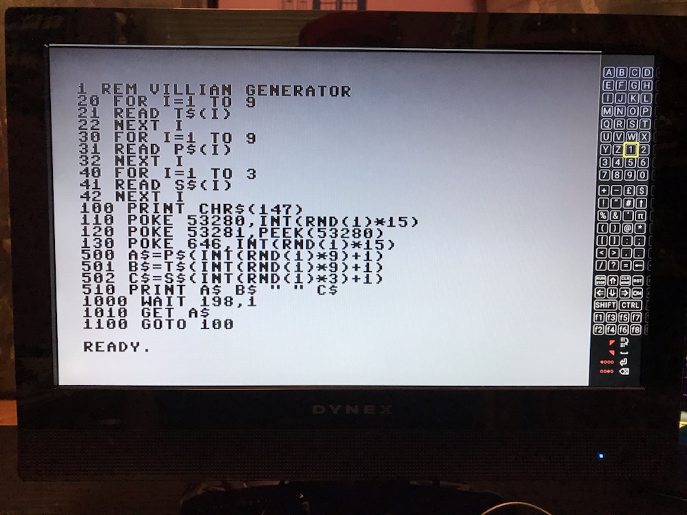
I started to see if I could manage without an actual keyboard. I did, but it was excruciatingly slow selecting letters from the virtual keyboard (on the right of the screen as shown above). But I had enough fun I went and bought a cheap usb keyboard to continue.
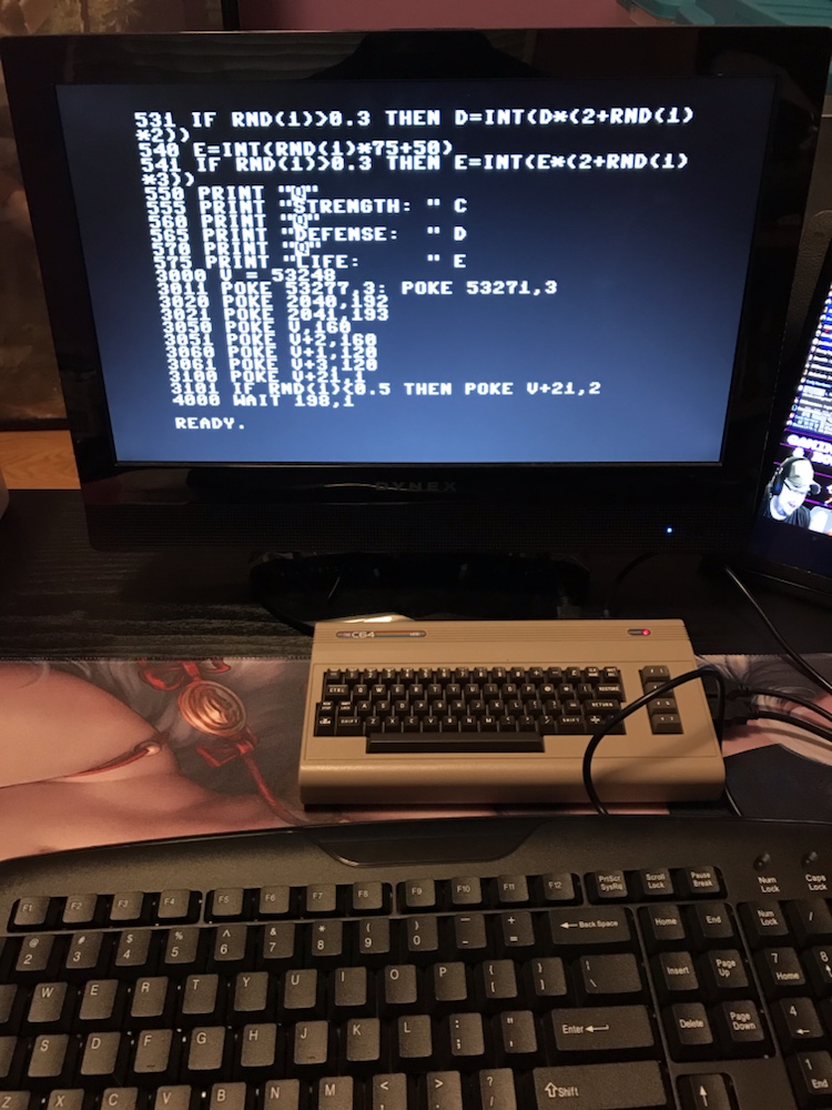
As you can see I’m working on a ‘villain generator’, the obvious first step towards the long-awaited next installment in the Mercenary King series. My program would generate an infinite amount of bad guys that could easily fit into any game!
It didn’t take long, and it worked! Here’s four examples of the infinite results:
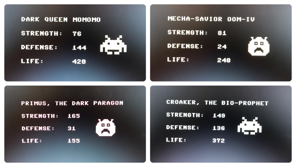
Unfortunately the lcd monitor I use doesn’t photograph well so you can’t appreciate the dazzling colour, but I’m sure you’re amazed by my amazing graphics? One of them I (may have) borrowed, but the other I designed from scratch! Here’s the sketchbook:
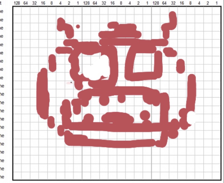
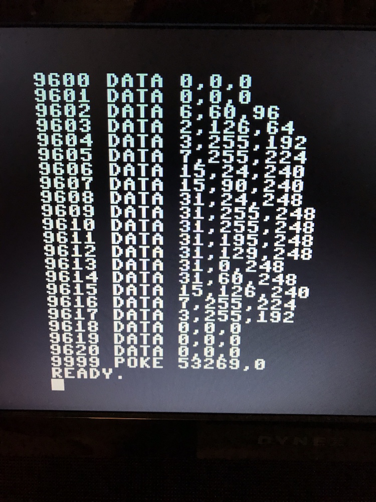
And here’s the sprite data in case you want to use it in your game:
Amazingly and coincidentally (*), while I was working on this I received a postcard that had this code on the back:
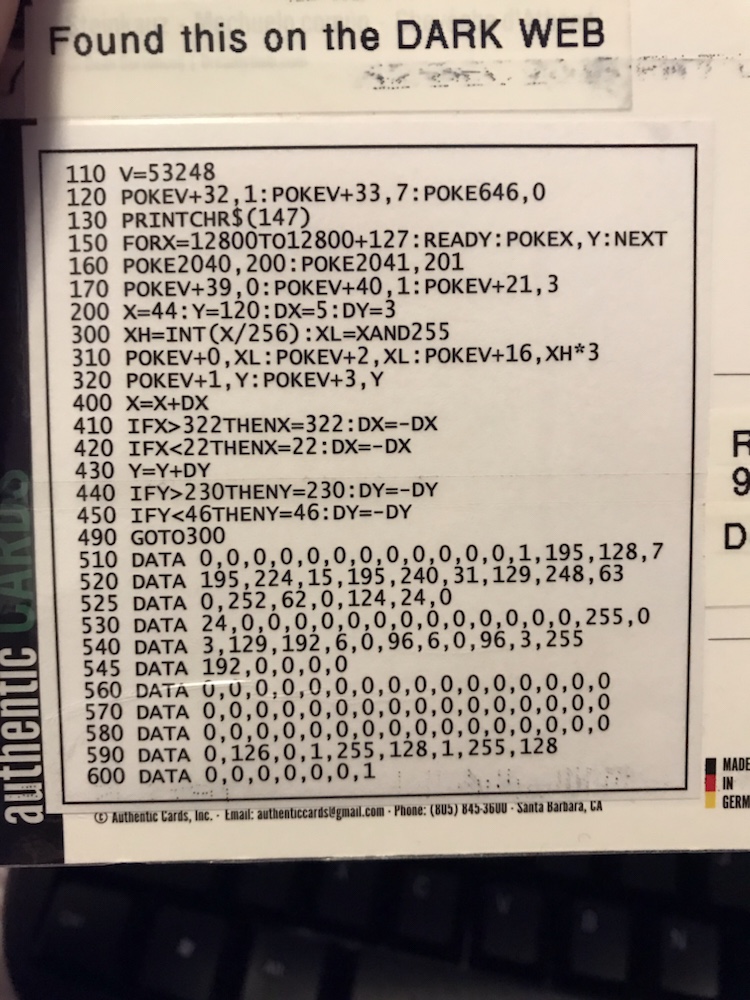
Naturally I had to type it in to see what it did…
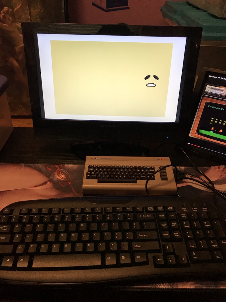
It was an animated Gudetama sprite! Unfortunately the postcard had no sender on it so I’ll never know who sent me this incredible demo ?
Anyway let me know if you need a villain for a game and I’ll let my C64 mini generate it for you…
(* I may have sent my brother code on a postcard in the past plus he loves Gude…)