In Inverness, a quick search on the information superhighway led me to a used game shop only a few hops and skips away from where we were staying. Of course we wandered over, and found a most intriguing and messy little shop full of records and games.The walls were decorated with album sleeves, mostly examples of 1970s Top Of The Pops ‘cover girl’ compilations like this:

There were loads of records and singles, and even a few cassettes. Disorder was the name of the game, and actually finding anything specific would have been a matter of luck. And yet I reckoned there were treasures in the boxes, and had I not been overseas I may have dug a bit through the vinyl.
Happily the games were sorted, but unfortunately 99% of them were 16 bit or older. I spied a few old Spectrum and CPC computer games, and may have even purchased them if they hadn’t been lacking their sleeves. There were no signs of actual 8-bit computers, or magazines from the 1980s. It looked like I would depart without making a purchase.
And then I saw this:
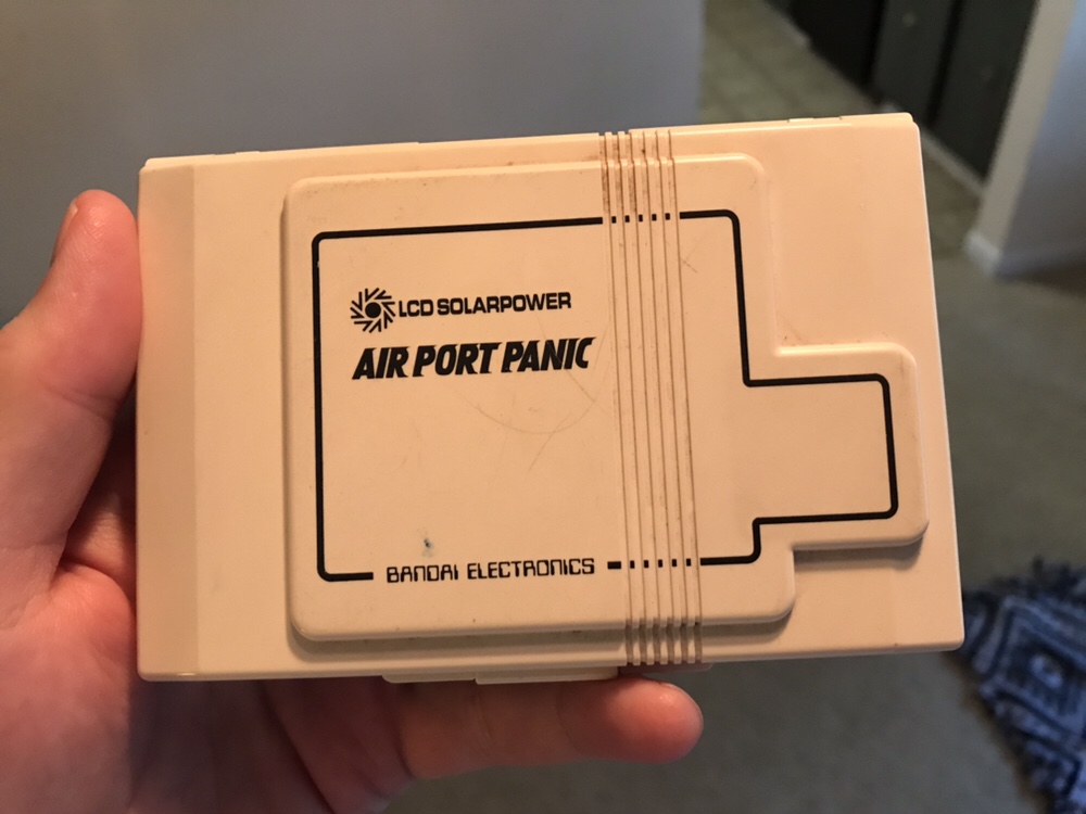
Its an LCD handheld from 1982! The last game in Bandai’s LCD Solarpower series to be precise, and one of the very few released outside of Japan. I’d never heard of this series of games before, and was intrigued to find that they rely completely on solar power to run.
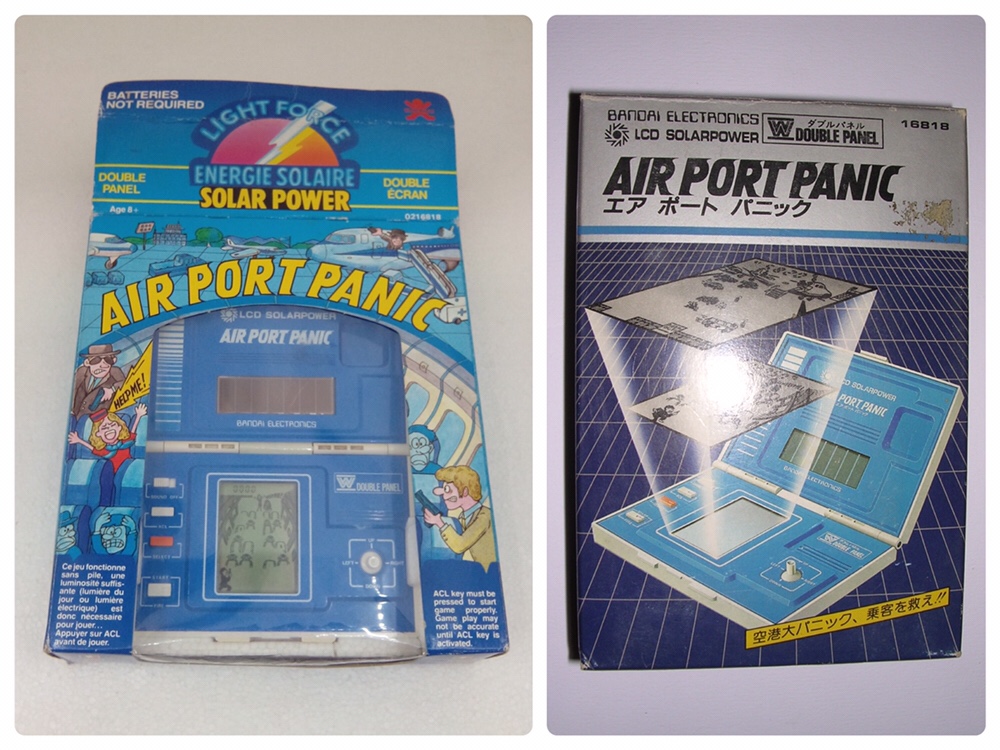
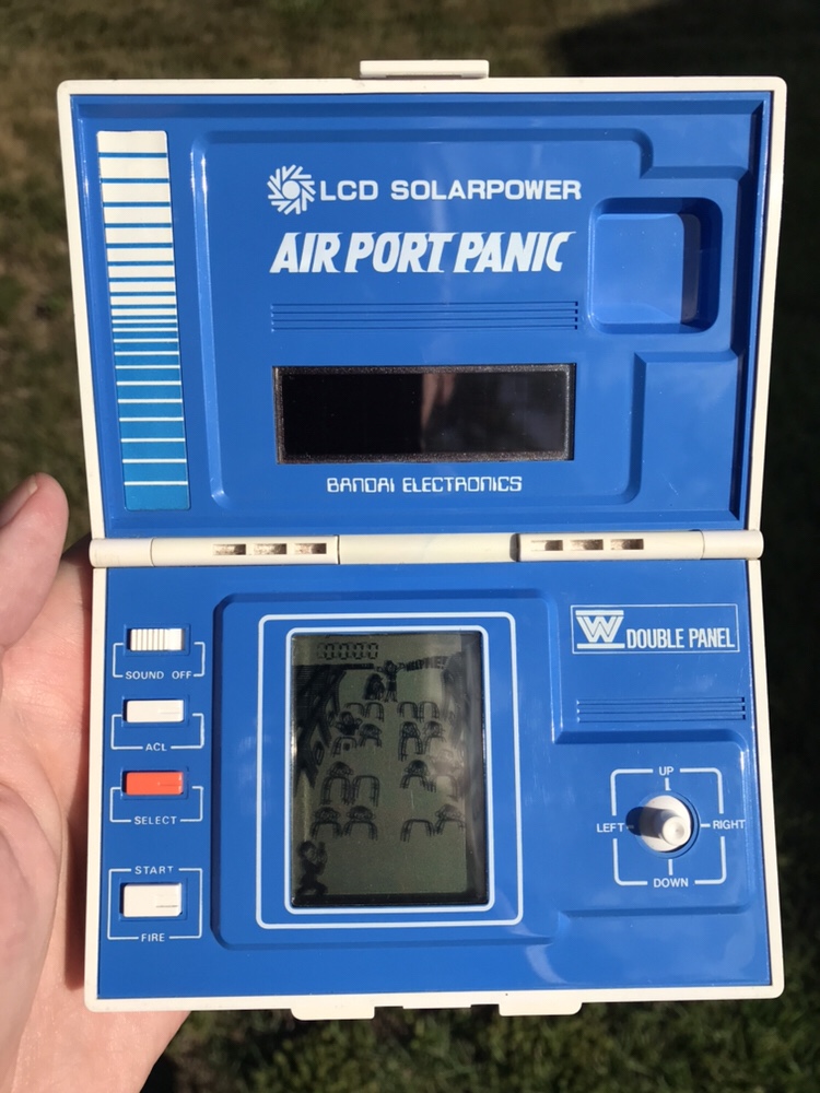
The Japanese box (mine didn’t come with the box) also shows how it has two layered screens for a very subtle 3D effect. This works well and makes the screens look busier than in the Game & Watch units from Nintendo.Unfortunately the technology requires actual solar power, and doesn’t function at all under artificial lighting!
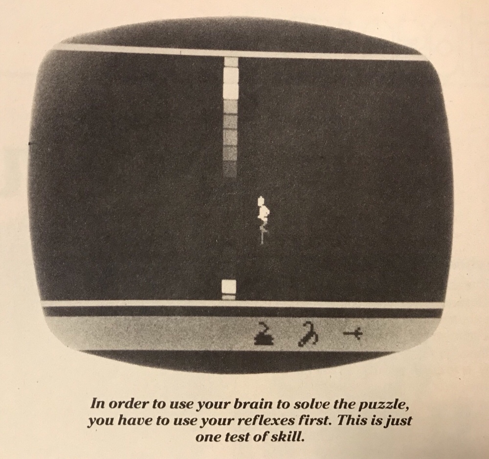
Furthermore, it’s incredibly difficult to get good photos due to how reflective the screen is, but here’s my best attempts:
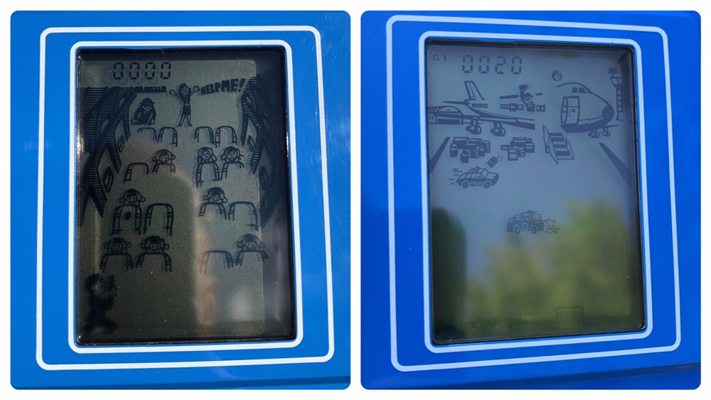
Air Port Panic is ridiculously difficult to the point where I suspect it’s slightly buggy. The action seems to lag the processor slightly and you seem to die moments before being hit by a projectile. But this can be accounted for somewhat, and success – reaching the hijacked plane in screen one and reaching the terrorists in screen two can be achieved with practice.
Sadky it’s not much fun, and not just because of the stupid difficulty. You also need to be standing in direct sunlight to play, and even then can hardly see the screen. I can see – impressive tech aside – why Bandai didn’t beat Nintendo in the early 80s handheld wars 🙂
I paid a mere £15 for this gem, which is considerably less than I see then for on eBay. As a game I’ll rarely return to it, but as another for the collection it was a happy find!