Category: Tech

The 30 year old Zoid

A few weeks back I went to a local convention and bought this:

IMG_6924

I’m sure I don’t have to explain why, but in case you’re having a senior moment…

This, my friends, is a Zoid. Specifically from the series called ‘Robo Strux’, which were the US Zoid rereleases from 1985. Zoids are robot animals (often dinosaurs or predatory cats) and I’ve always liked their design. As a child we were too poor for me to ever own one, but I’ve been remedying that in recent years! I was agog to see such an old one for sale at my local con, and my agog-level doubled when I discovered it was unmade. A quick ebay search told me his price (at which I first baulked) was low, so I snapped it up. I was a very happy man that day.

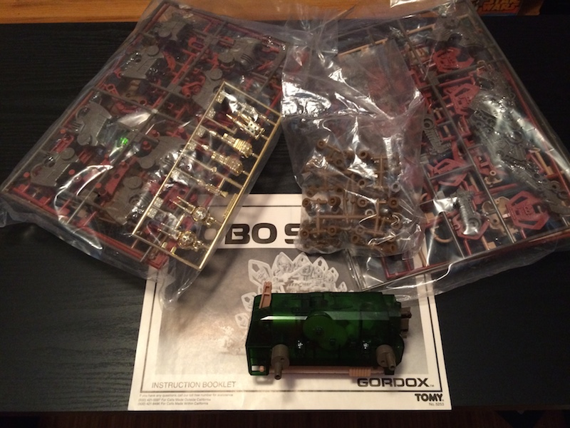
Unquestionably the value of this product was mostly due to the fact it was still unmade and almost complete (only the sticker sheet was missing). Were I a fanatical collector, I would have put it somewhere safe and been happy in the knowledge I owned it. But I bought it to make it, and this past weekend I did. Here’s what was inside the box:

IMG_6925

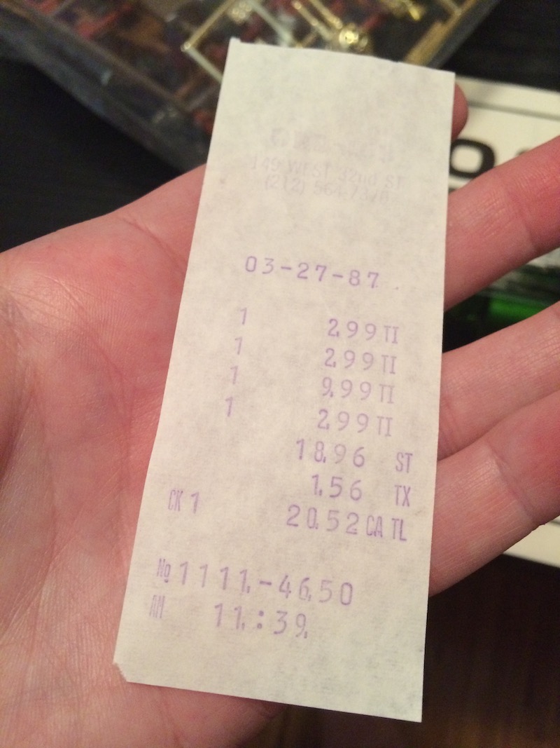
And this was between the pages of the manual:

IMG_6926

So it was purchased in NYC back in March 1987, almost certainly for $9.99. That’s about $21.50 in todays money. Which is much less than I paid 🙂

IMG_6933

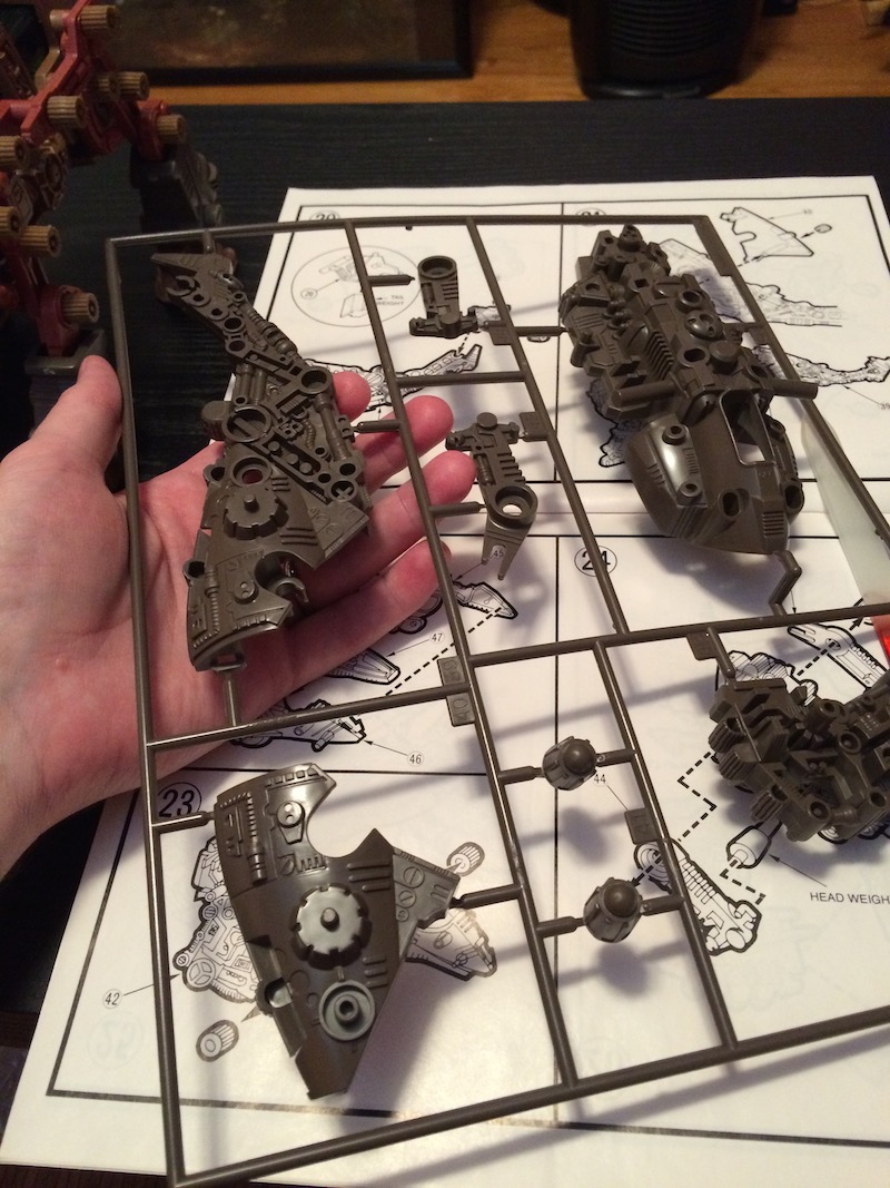
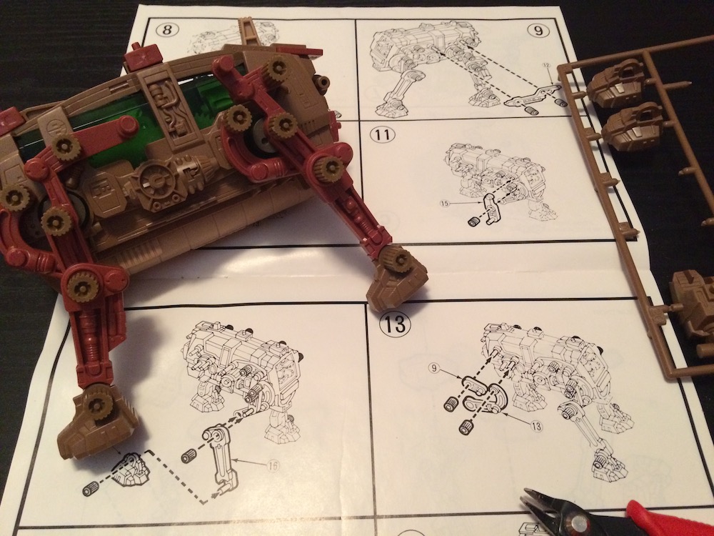
The basic construction of the kits is remarkably similar to today’s models. There were several runners, molded in 5 different colours. It was snap together, and very easy to assemble with only cutters and a file (to remove the flash). However since the model is motorized and the legs need to move, some pieces were loose against each other and held on by interesting rubber caps:

IMG_6930

Even after 30 years, the rubber was still perfectly pliable.

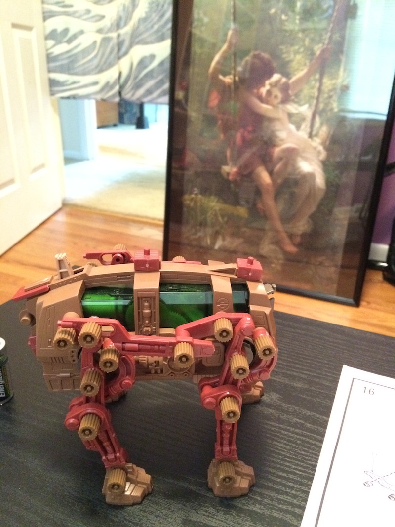
As a kit designed for children, there weren’t nearly as many pieces as one of the ‘High Grade Master Model’ kits I’ve been buying recently, but there were still enough to make it interesting and fun. The design was very clever, especially of the legs. Here he is the first time he was able to stand up:

IMG_6932

Assembly took me about an hour, and was great fun. I wish the dude at the con had had more of these buggers for sale!

IMG_6935

And here he is finished:

IMG_6936

Oooh! Dangerous and mighty he looks, but Gordox (or more correctly Gordos) is apparently a specialized command unit more useful for his long-range sensor and communications than his offensive abilities.

He’s also a bit slow…

Isn’t he cute!

The Nixie Clock

nnn

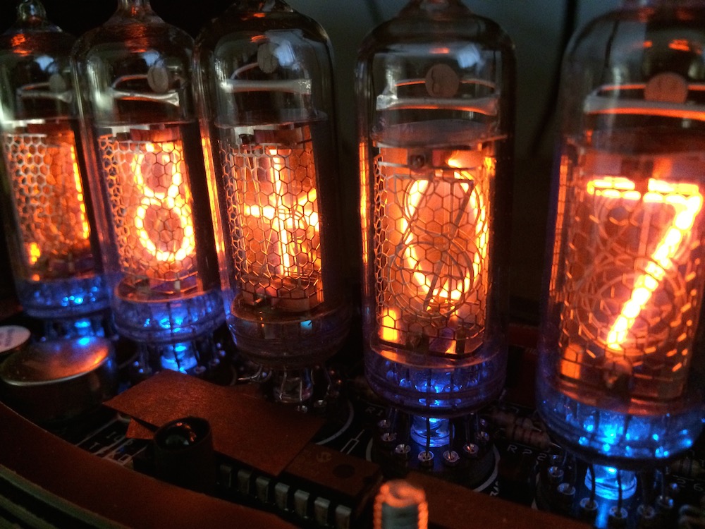
Nixie tubes were invented in 1955 and were a popular pre-digital form of displaying numerals in electronic circuits. They use a technology somewhat similar to neon lights, and are designed so the shape of the discharge corresponds to numbers (or rarely letters). They were obsoleted in the 1970s by LCD displays, and even more so in the 1980s by pixel displays.

But they have experienced a bit of a resurgence in recent years since they are so pretty, and so retro. It is a great regret of mine that several years ago, while cleaning out old lab equipment at school, I discarded a (broken) nixie geiger counter from the 1960s. I should have kept it, and fixed it!

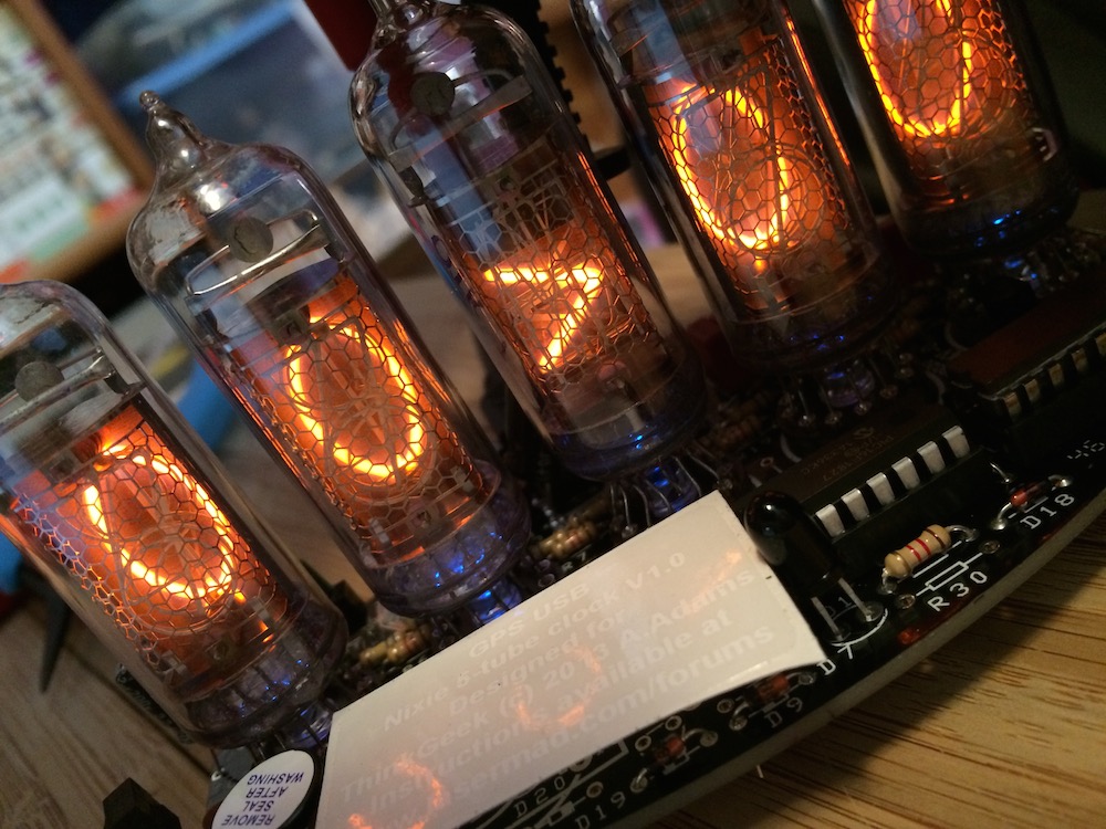
And then this year, for my birthday, KLS purchased me a Nixie clock do-it-yourself kit. I made it this past week, and it was easily the most challenging kit of any kind that I have ever made.
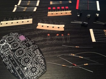
IMG_6440

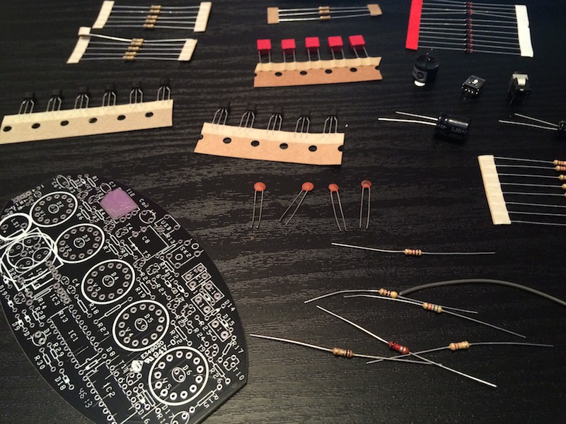
It starts with the above – many components, an empty printed circuit board (PCB) and a whole lot of fitting and soldering to be done. Now I’m not the biggest fan of soldering, and despite once being paid to teach others how to do it (hi Florence!) I don’t consider myself very good. But I borrowed an iron from school, prepared a comfortable work surface and started…
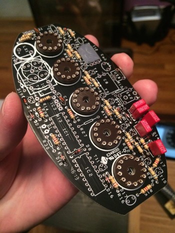
IMG_6446

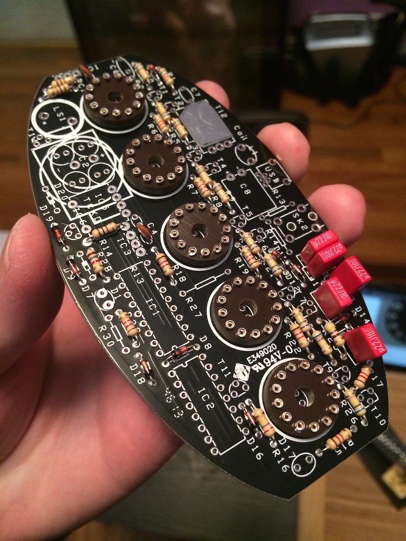
That’s about 3 or 4 hours later. Most of the resistors are in place, as well as the diodes and all the capacitors. I believe, at this point, I had soldered over 170 connections. It turned out to be easier than I thought, but at the same time very detailed work. If I didn’t have any experience at all, it would have been almost impossible to do it correctly due to how close some connections were.

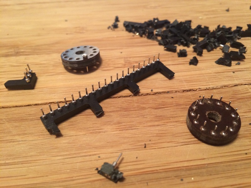
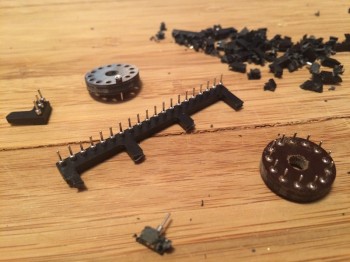
The hardest thing to this point was actually preparing the nixie mounts. This photo shows the process:
IMG_6445

The circular bakelite discs had to have the conductive pins pushed into them and then the whole thing was soldered to the PCB. The difficulty was the pins were molded inside plastic and you had to break them out. This was much harder than it should have been and I cut myself more than once. It was frustrating but I got it done.

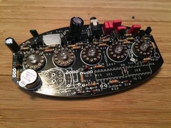
The next step was to add the LEDs:
IMG_6449

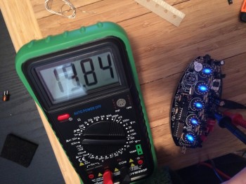
Then a few more components (including the chips) before testing to see if everything had been done correctly:
IMG_6455

The relief I felt at this point was incredible. This was during the second day of assembly, after a half dozen hours or so. I’d been frustrated up and down by this point since the ‘instructions’ for the kit consisted of a series of forums posts on a website that were lacking (in my opinion) in certain pieces of information that would have made things much easier had I known them in advance.

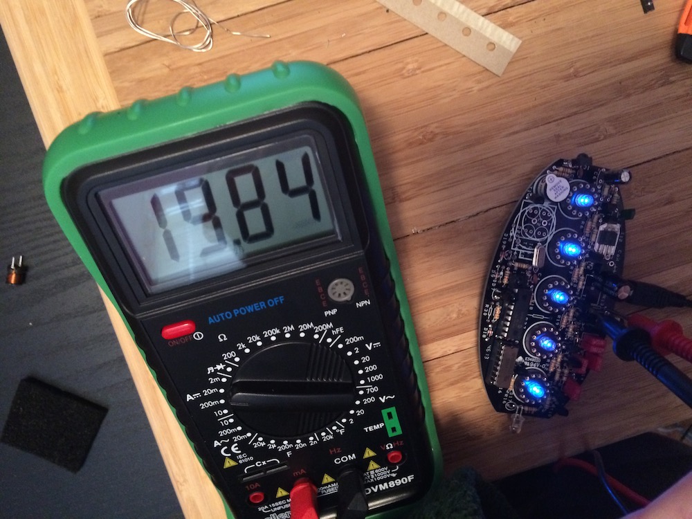
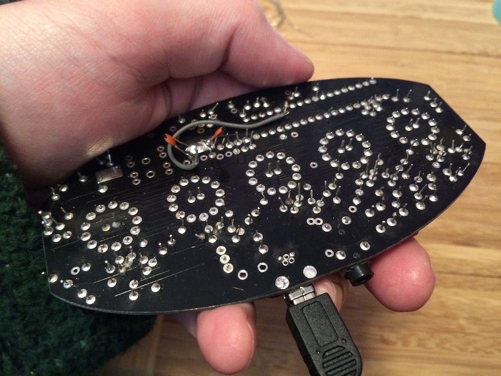
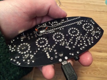
But I was half way through the PCB assembly and it was working (the LEDs were lit and the current was ~20 mA). Here’s the back of the kit at this point:
IMG_6452

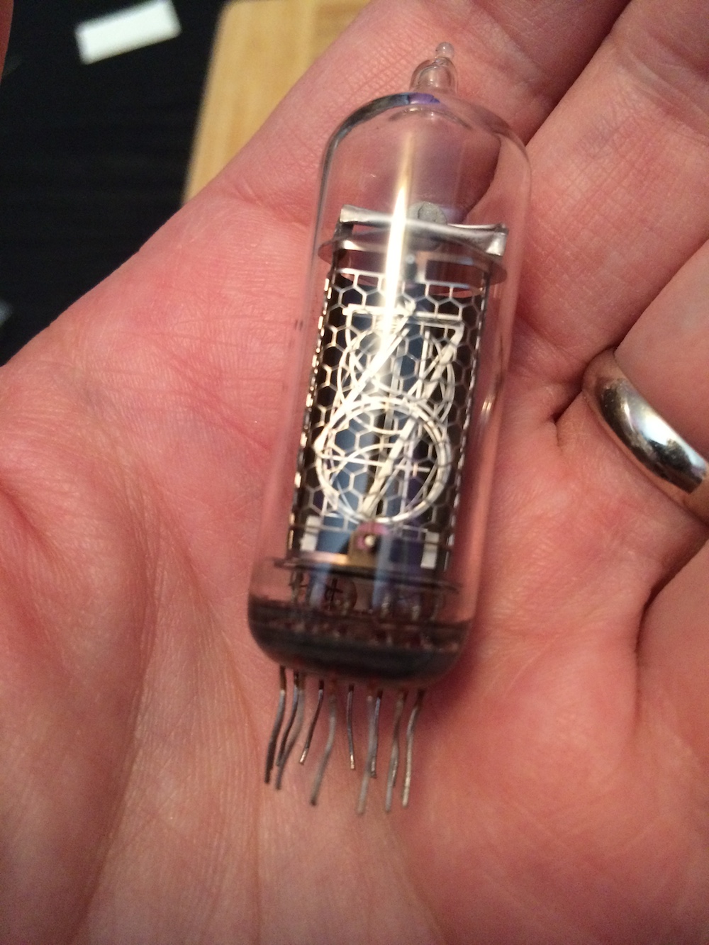
The next step was to add the nixies, as well as the other essential components to actually make it a clock (motion sensors, crystal, battery backup etc.). Here’s one of the nixies:
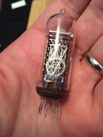
IMG_6463

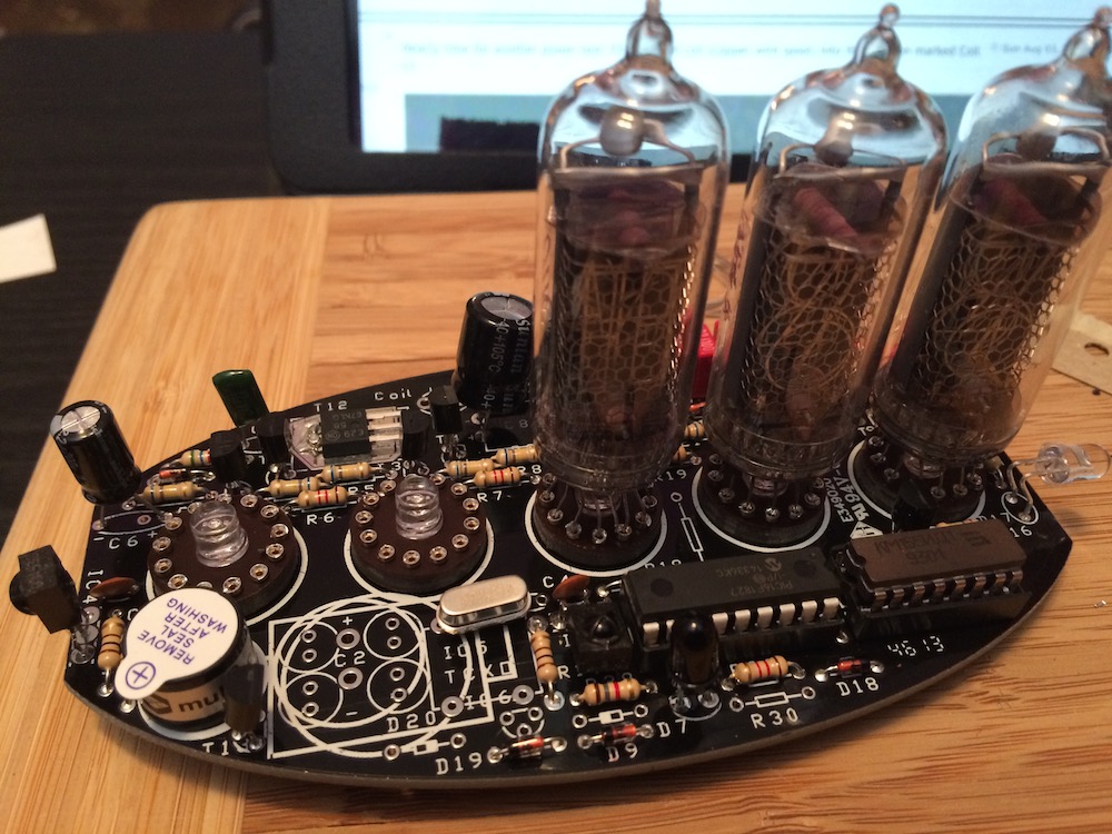
The kit comes with five in total: four numeric and one symbolic (+,-.>.<). Putting the 13 leads into the sockets on the PCB was easily the hardest and most frustrating part of the entire kit, and took about an hour in total for all five. Here we are mid-process:
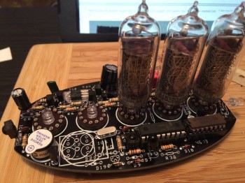
IMG_6464

And when it was done – time to test it all:
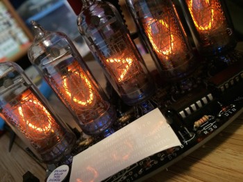
IMG_6466

OMG it works! I was super relieved here – everything lit up as it should have and the whole thing seemed to work. Little did I know I still had a lot ahead of me.

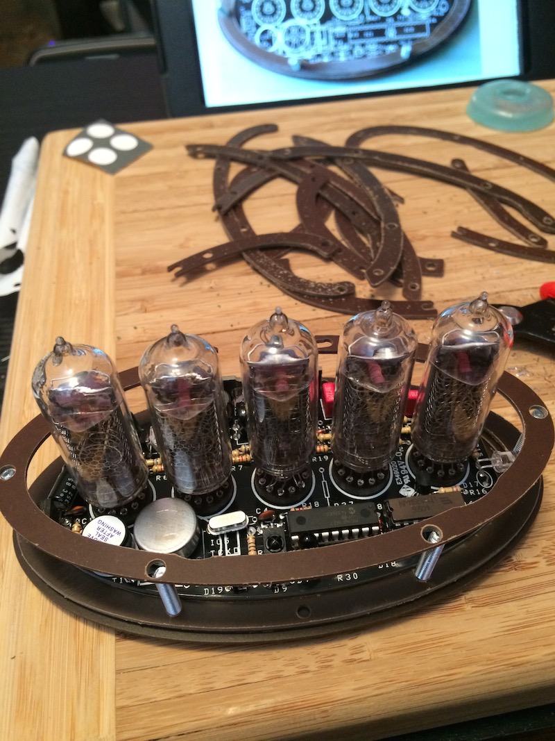
Next I had to start building the case. Unfortunately two pieces were received broken, and a third was miscut. The case as a whole was poorly designed, and the pieces didn’t fit together anywhere near as good as I feel they should have. I had to do a lot of sanding and drilling to get things looking acceptable (but as you see later, believe I mostly succeeded). Again, a complete beginner would have been in trouble in this step. Here’s a shot mid case assembly:
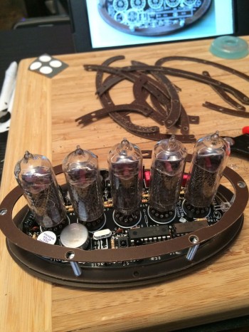
IMG_6468

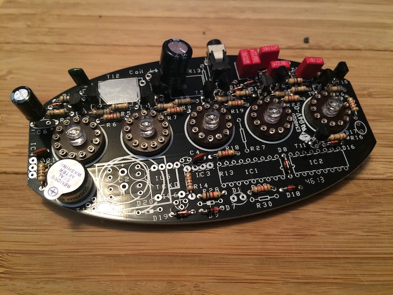
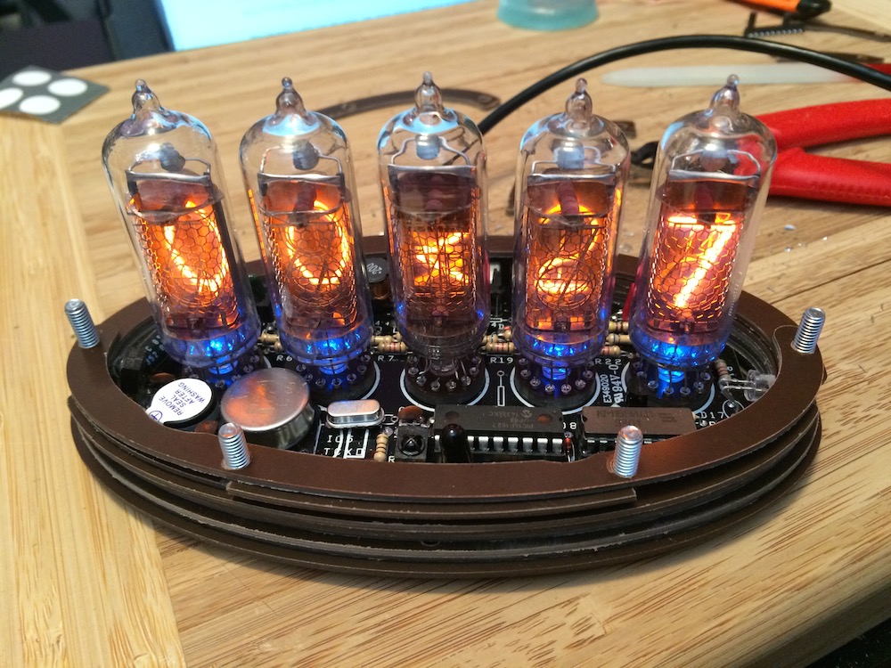
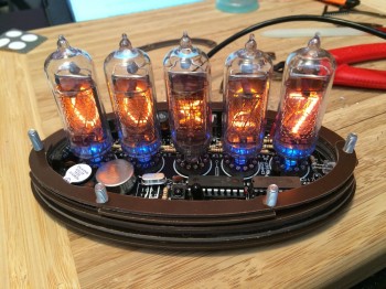
The five blue LEDs are asthetic, and you can see in the photo two above that they are all on (under the nixies). That was the last photo taken of them on, because for reasons unknown after I soldered the final component (the backup capacitor battery) and put it in the case the middle LED stopped working. Here’s a photo of the clock – all wiring completed – showing this (the case is not yet complete):
IMG_6469

In the front, just to the left of one of the chips, you can see a black LED. Right behind that (slightly up left) is a sensor chip. These two parts are required to set the clock, which uses a virtual motion controlled ‘air switch’ to set features like time, date, 24-hour mode, alarm etc. It’s a remarkably full-featured clock, but mine had a big problem: the motion sensor barely works.

It took me endless trial-and-error to get the switch working, entailing making IR blocks out of black-colored paper and moving my hand around like a deranged puppet for about an hour trying to control the ultra-unresponsive switch. Countless times during this process I lamented the fact the designer didn’t just choose to add buttons. But eventually I got the time set, and now – five days later – the clock continues to keep perfect time.

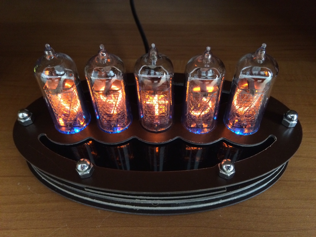
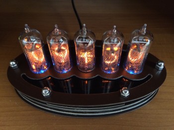
Here’s a shot of my completed clock:
IMG_6500

I think I did very well in hiding the breaks in the case, and I think the middle LED being burned out is mostly unnoticeable. In fact I think it looks very nice, and certainly is very striking in our entertainment center under the TV where it glows impressively in the dark.
IMG_6478

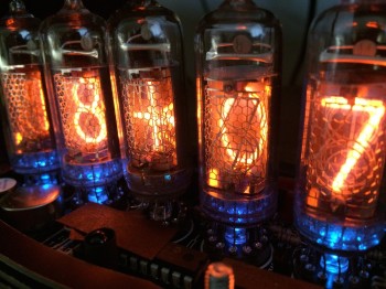
The nixies are very, very pretty aren’t they. This shot is with the cover (of the case) of, and you can see a piece of blackened paper I have resting over the sensor to prevent it from flaking out again. The clock is permanently set to 24 hour time, and the middle nixie alternates between – and + every second. It’s quite lovely.

It was an extremely difficult and frustrating kit to build, and I don’t think it’s probably worth what it cost. But I did my very best, and it works and looks quite good, so in the end I’m quite happy with my new nixie clock 🙂


How Far Can You See In The Woods (part 2)

If you’ve been reading the comments of the previous blog post, you will have seen Bernard coded the simulation I described. You can play with it here. This simulation doesn’t answer the original ‘field problem’, but instead the more general problem of ‘can you see your friend if you’re both standing in a forest’?

{A quick note: if it appears to crash your browser, just force-quit because the code is in an infinite loop. This happens a lot with high wood density and low tree radius. On an ipad, force-quit by returning to the home screen then double tapping the home button and swiping the browser up to close it.}

I’ve done some analysis using this early version of the simulation, and here’s a table of results:

Screen Shot 2015-03-14 at 8.24.51 AM

That’s a surface plot of the percent chance to see your friend indexed by wood density (0.1 = 10% trees) and tree radius. A few comments:

– The distance between you and your friend is randomized.
– The tree position is randomized.
– The tree radii are unphysical, and the code doesn’t seem to support non-integer (cm) values.- I used 2500 trials each, except when radius was low (percentage ~ 0) where I dropped to 250.

Interestingly you can see the percent chance increases with tree size, but decreases with wood density. You are more likely to be able to see your friend if the trees are large, and less likely if they are close together. Currently there is no upper-bound on tree size, and it seems the percent chance simply increases as they get bigger and bigger.

As for the distance question, I’m happy to report that Bernard also added metrics to help you calculate this. I’m going to pick 20% wood density and 7m tree radius (!!) as an example. Here’s a simple representational plot of one such forest complete with friends:

Screen Shot 2015-03-14 at 8.20.23 AM

In the above – generated by the simulation – the friends are far apart and can’t see each other. The obvious question is what is the relationship between distance and ability to see each other, and here are the metric results from 1000 trials with these parameters:

Screen Shot 2015-03-14 at 8.20.38 AM

We can’t read too much into these since position is randomly chosen, but on first glance it seems (in this case) the friends were more likely to see each other at about 50 meters. However if you look at the bottom plot, you’ll notice there were quite a few occasions around the 50m mark where they could not see each other. I’d estimate about 20 or so, which means only about a 60% chance (seen/total) of seeing each other at about 50m. Glancing at the two plots it is, as we’d expect, the case that the chance to see each other decreases with any distance beyond standing adjacent.

So the results are interesting, but these are early days yet. Were I to modify the current code, here’s what I would do:
– Input wood density input as an integer between 1 and 99
– Input tree radius in cm
– Output result plots as percent chances per distance – one plot, rather than two, of (times seen at that distance)/(total times separated by that distance)
– Add variable tree radii
– Add foliage transmission support- Make the map circular, and distribute the trees according to a Gaussian distribution (this is more physical) {This may be for V2.0}

If and when these adjustments are made, you may see part 3 of this post 🙂